The QSPI peripheral can work in two modes:
- In the first mode, you can just access the memory with functions like read, write, and erase.
- In the second XiP (eXecution in Place) mode, your QSPI memory is cast to an MCU unified address space to address 0x12000000.
This getting started guide describes how to configure a QSPI device, program it, and start the Blinky application.
Prerequisites
You must first test the setup of your toolchain. To do so, compile, program, and run a very simple example that does not use a SoftDevice, for example the Blinky SysTick Example.
Use the PCA10056 board in version 0.10.0 or higher.
Make sure that you have all the required tools installed and that the board is connected to your computer. See Getting started page (for nRF52840) or Setting up the development kit (for nRF52832) for more information.
Procedure
This procedure requires programming your development kit with two examples. You must download the Blinky application to the QSPI memory and the main memory must be programmed with the bootloader application.
- Open the Blinky SysTick Example directory and then open the
pca10056_qspi\blank\armgccdirectory. - Run the commandto compile and flash the QSPI memory device with the Blinky application.make flash
- Open the QSPI bootloader Example directory.
- Compile the bootloader code and flash the board using one of the provided toolchains in the pca10056 directory.
Alternatively, you can compile the application using make and use the nrfjprog tool to program the device:
- Find the compiled HEX file and program the QSPI memory flash using nrfjprog command: nrfjprog --family NRF52 --program nrf52840_xxaa.hex --qspichiperase
- Verify the previous step with the command: "Verified OK." message should be displayed.nrfjprog --family NRF52 --verify nrf52840_xxaa.hex
After completing these steps, LEDs will be blinking on your development kit. In case of problems, see Troubleshooting.
Preparing an application to work with QSPI XiP
The code is executed from QSPI memory a few times slower than the code executed from internal flash. For this reason, avoid using frequency-related solutions in code, for example delay loops based on dummy instructions. They will be inaccurate.
- Move the flash in your application linker script to adress 0x12000000. To do this in GCC projects:
- Open the
*.ld file. - Find the line: FLASH (rx) : ORIGIN = 0x0, LENGTH...
- Change the line to the following: FLASH (rx) : ORIGIN = 0x12000000, LENGTH...
- Recompile your application.
- Program and verify the application in QSPI memory device using the command from section Procedure.
- Open the
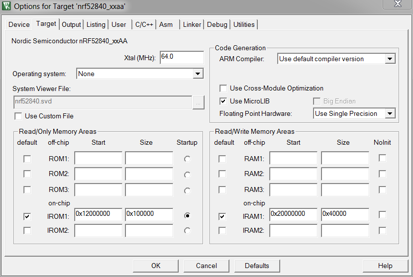
- Reconfigure a Keil project in project options. Then, program the HEX file and verify it using the command from section Procedure. Keil does not navitely support programming of a QSPI memory device.
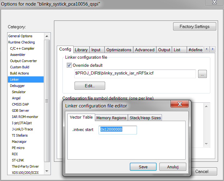
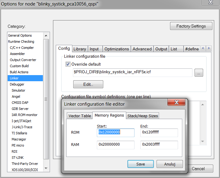
- Reconfigure an IAR project in project options, as shown below. Then, program the output HEX file and verify it using the command from section Procedure. IAR does not navitely support programming of a QSPI memory device.
Preparing the bootloader
Bootloader is an important part of the QSPI XiP solution. It configures the QSPI peripheral, the memory device, and jumps to the 0x12000000 address. To create your own bootloader, you can use the QSPI bootloader Example as a reference design.
Troubleshooting
Check the following table for the list of known issues and available workarounds.
| Issue | Workaround |
|---|---|
| The application cannot be downloaded to external memory device. | Check connection, length of lines, and device family code. This getting started guide and examples use the configuration for full speed mode for the MX25R6435F device. For other devices, you must change the QSPI configuration in nrfjprog file QspiDefault.ini in the nrfjprog installation directory or prepare your own one. |
| The application can be downloaded to the external memory device but verification fails. | There might be a problem with connection between the memory device and the MCU. Check the connections. If the problem still exists, try slowing down the download process. You can also use a simpler mode to access the memory device. To do this, open the QspiDefault.ini file in the nrfjprog installation directory(or prepare your own one) and use a safer configuration. For example:ReadMode = FASTREAD WriteMode = PP Frequency = M2
|
| The application can be downloaded and is verified but nothing has happened. | Check whether you moved the flash address to 0x12000000 in your application linker script. The issue can be also related to data distortion. Try slowing down the memory device in the bootloader sdk_config file. Find QSPI_CONFIG_FREQUENCY and set it to 15. |
| Debugging the QSPI application. | You can debug your QSPI application like a flash one. Remember not to load application code to the SoC in a debug session. |