The nRF52 PDK has an I/O expander to avoid conflicts with boards that follow the Arduino standard, the on-board GPIOs for the buttons and LEDs would otherwise possibly conflict with such boards.
| GPIO | Part | Arduino signal |
|---|---|---|
| P0.13 | Button 1 | 2 |
| P0.14 | Button 2 | 3 |
| P0.15 | Button 3 | 4 |
| P0.16 | Button 4 | 5 |
| P0.17 | LED 1 | 6 |
| P0.18 | LED 2 | 7 |
| P0.19 | LED 3 | 8 |
| P0.20 | LED 4 | 9 |
The I/O expander will release these GPIOs for general use when the nRF52 PDK is used together with boards that follows the Arduino standard. The I/O expander can be permanently enabled by shorting solder bridge SB18 or permanently disabled by cutting the shorting track on SB19. You must also short SB18 when cutting SB19 for full compatibility with the Arduino standard.
The I/O extender can be temporarily enabled by connecting SHIELD DETECT to ground.
Figure 1. Enable or disable I/Os for Arduino standard

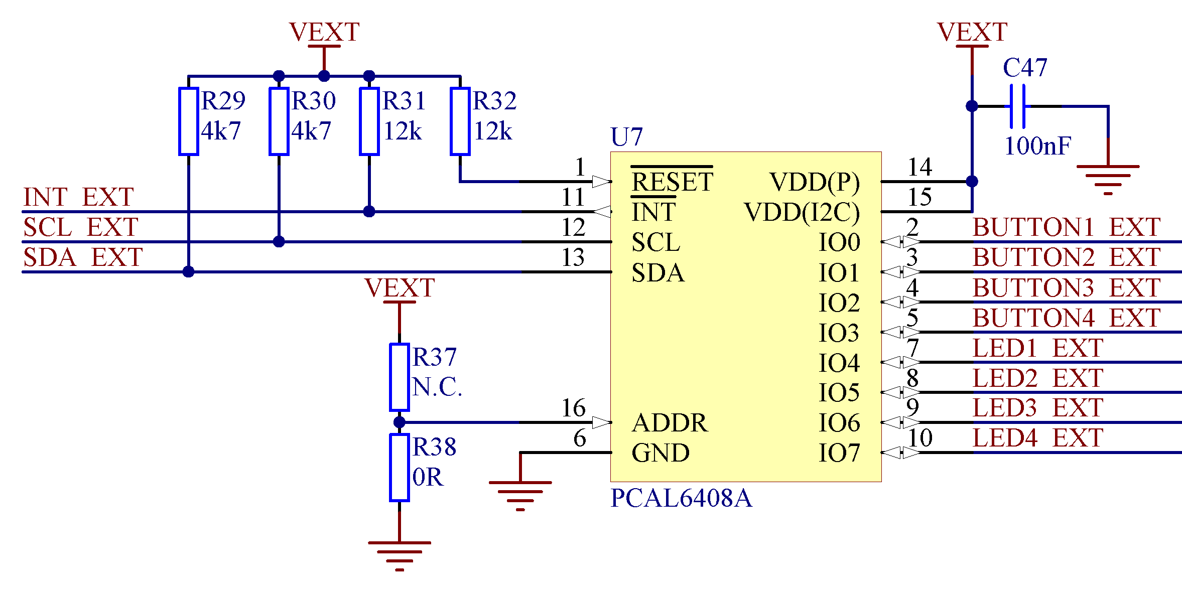
In addition to the buttons and LEDs, the following GPIOs are used for the I/O expander:
| I/O expander signal | GPIO |
|---|---|
| /INT | P0.17 |
| SDA | P0.26 |
| SCL | P0.27 |
Figure 2. I/O expander schematic
Important: SW debouncing should not be needed when using the I/O expander. Each button
on the nRF52 PDK is
equipped with a debouncing filter.