The four buttons and four LEDs on the nRF52 PDK are connected to dedicated I/Os on the nRF52832 chip.
| Part | GPIO | Short |
|---|---|---|
| Button 1 | P0.13 | - |
| Button 2 | P0.14 | - |
| Button 3 | P0.15 | - |
| Button 4 | P0.16 | - |
| LED 1 | P0.17 | SB5 |
| LED 2 | P0.18 | SB6 |
| LED 3 | P0.19 | SB7 |
| LED 4 | P0.20 | SB8 |
If GPIO P0.17–P0.20 are needed elsewhere, the LEDs can be disconnected by cutting the short on SB5–SB8, see Disconnecting the LEDs. The LEDs and buttons can also be disconnected by using the I/O extender as described in I/O expander for buttons and LEDs.
Figure 1. Disconnecting the LEDs

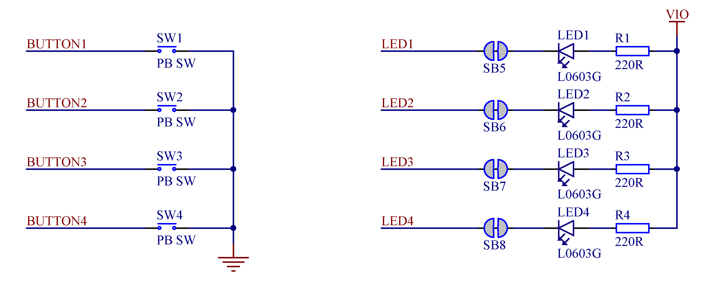
The buttons are active low, meaning the input will be connected to ground when the button is activated. The buttons have no external pull-up resistor, so to use the buttons the P0.13–P0.16 pins must be configured as an input with an internal pull-up resistor.
The LEDs are active low, meaning that writing a logical zero ('0') to the output pin will illuminate the LED.
Figure 2. Button and LED configuration