The bootloader module is responsible for:
- booting into an application,
- activating new firmware,
- optionally, entering DFU mode where DFU transports are activated and new firmware can be delivered,
- feeding the watchdog timer.
Each bootloader example provided in this SDK contains one DFU transport.
For an overview of its API, see Bootloader modules.
Bootloader Settings page
A page in non-volatile memory (see Memory layout) is used to keep the bootloader and DFU information. The settings page contains information about:
- current firmware - size, CRC-32,
- pending firmware - size, CRC-32,
- progress of the firmware update,
- progress of the firmware activation,
- current firmware versions (application and bootloader),
- transport-specific data.
Firmware activation
Firmware activation is the final step of the firmware update process. The activation is triggered based on the information in the settings page that is read during boot-up. Firmware activation involves copying the new firmware in place of the exitsing one (in case of application dual-bank update - see Dual-bank and single-bank updates), and updating the settings page to allow the new firmware to boot. The bootloader ensures that copying is power fail-safe. In case of updating bootloader, MBR feature is used to perform power fail-safe copy (SD_MBR_COMMAND_COPY_BL).
DFU mode
In the DFU mode, the bootloader activates the DFU transports and the device is ready to receive new firmware. The bootloader enters the DFU mode on the following conditions:
- No valid application is present.
- SoftDevice is activated and a valid application is present. In that case, the bootloader expects that an application update can be requested by the host.
- Entering DFU mode is triggered by one of the optional sources:
- Button (NRF_BL_DFU_ENTER_METHOD_BUTTON),
- Pin reset (NRF_BL_DFU_ENTER_METHOD_PINRESET),
- Special value in GPREGRET register (NRF_BL_DFU_ENTER_METHOD_GPREGRET),
- Request from the application written to the settings page (NRF_BL_DFU_ENTER_METHOD_BUTTONLESS).
When the DFU mode is entered, the inactivity timer is started. On timer expiration, the bootloader resets. The inactivity timer is restarted on any DFU activity. The inactivity timeout is by default set to NRF_BL_DFU_INACTIVITY_TIMEOUT_MS. If the DFU mode is entered after the SoftDevice activation, then the timeout is set to NRF_BL_DFU_CONTINUATION_TIMEOUT_MS.
Starting the application
Based on information from the settings page, the bootloader determines whether the application exists and where it is located. The bootloader checks the integrity of the application before starting. Optionally, the integrity check can be skipped in certain cases to reduce boot-up time (NRF_BL_APP_CRC_CHECK_SKIPPED_ON_GPREGRET2, NRF_BL_APP_CRC_CHECK_SKIPPED_ON_SYSTEMOFF_RESET). If one of the following conditions occurs, the bootloader enters the DFU mode:
- no application is installed,
- the integrity check fails,
- there is no settings page.
Watchdog timer support
The bootloader detects whether the watchdog timer (WDT) is active and feeds it to prevent watchdog reset.
Bootloader dependencies
Bootloader modules, except for the transports, do not depend on the SoftDevice. Only the BLE DFU transport (see BLE) depends on the SoftDevice.
The bootloader supports the case where SoftDevice is not present in the system at all.
Programming the bootloader
During the system startup, the Master Boot Record (MBR) is responsible for starting the bootloader if a bootloader is installed. To do this, the MBR must know the start address of the bootloader. This start address is defined in either the MBR itself, or in MBR_UICR_BOOTLOADER_ADDR. This must be set to the correct value when you program the bootloader. See the S132 SoftDevice Specification for more details. The bootloader, by default, places its start address in MBR_UICR_BOOTLOADER_ADDR, and during the first boot it writes its start address to MBR_BOOTLOADER_ADDR.
Programming the bootloader requires the following steps:
- Erase the device.
- Program the SoftDevice. See Programming SoftDevices for instructions.
- Compile the bootloader.
- Program the bootloader. See the following sections for instructions for Segger Embedded Studio, Keil, IAR, and nrfjprog directly (if you are using GCC).
Programming using Segger Embedded Studio
No additional action is required since softdevice and UICR are programmed implicitly by Segger Embedded Studio when bootloader application is flashed.
Programming using Keil
You cannot write to MBR_UICR_BOOTLOADER_ADDR when using the default J-Link target driver in Keil. Therefore, you must configure Keil to use an external tool, nrfjprog. To do so, select Project > Options for Target 'xxx' and configure nrfjprog.exe as the tool for flash programming. nrfjprog.exe is installed with the nRF5 MDK and must be in the Windows system path. The following screenshot shows the required settings for nrfjprog.exe:
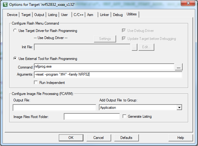
After configuring the flash command, program the bootloader as you would do with a normal application. If several J-Link emulators are connected, select the one that contains the nRF5 IC that you want to flash.
Programming using IAR
You cannot write to MBR_UICR_BOOTLOADER_ADDR when using the default J-Link target driver in IAR. Therefore, you must set up nrfjprog as an external tool. To do so, select Tools > Configure Tools. nrfjprog.exe is installed with the nRF5 MDK and must be in the Windows system path. The following screenshot shows the settings for nrfjprog.exe:
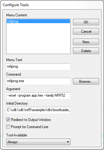
Change "app.hex" to the file name of your HEX file and the initial directory to the directory that contains the HEX file. After configuring the flash command, program the bootloader as you would do with a normal application. If several J-Link emulators are connected, select the one that contains the nRF5 IC that you want to flash.
Programming using nrfjprog directly
You can also program the bootloader using nrfjprog directly from the command line. To do so, run the following command:
Change "application.hex" to the file name of your HEX file.
Memory layout
When adding a bootloader to your device, you must be aware of where in the device memory the different firmware components are located.
The following table shows the memory layout for the different chips with current SoftDevices:
| Usage | Memory range nRF52832 (S132 v7.0.x) | Memory range nRF52840 (S140 v7.0.x) | Memory range nRF52810 (S112 v7.0.x) | Memory range nRF52833 (S113 v7.0.x) | Memory range nRF52833 (S140 v7.0.x) |
|---|---|---|---|---|---|
| Bootloader settings | 0x0007 F000 - 0x0008 0000 (4 kB) | 0x000F F000 - 0x0010 0000 (4 kB) | 0x0002 F000 - 0x0003 0000 (4 kB) | 0x0007 F000 - 0x0008 0000 (4 kB) | 0x0007 F000 - 0x0008 0000 (4 kB) |
| MBR parameter storage | 0x0007 E000 - 0x0007 F000 (4 kB) | 0x000F E000 - 0x000F F000 (4 kB) | 0x0002 E000 - 0x0002 F000 (4 kB) | 0x0007 E000 - 0x0007 F000 (4 kB) | 0x0007 E000 - 0x0007 F000 (4 kB) |
| Bootloader | 0x0007 8000 - 0x0007 E000 (24 kB) | 0x000F 8000 - 0x000F E000 (24 kB) | 0x0002 8000 - 0x0002 E000 (24 kB) | 0x0007 8000 - 0x0007 E000 (24 kB) | 0x0007 8000 - 0x0007 E000 (24 kB) |
| Application area (incl. free space) | 0x0002 6000 - 0x0007 8000 (328 kB) | 0x0002 7000 - 0x000F 8000 (836 kB) | 0x0001 9000 - 0x0002 8000 (60 kB) | 0x0001 C000 - 0x0007 8000 (368 kB) | 0x0002 6000 - 0x0007 8000 (328 kB) |
| SoftDevice | 0x0000 1000 - 0x0002 6000 (148 kB) | 0x0000 1000 - 0x0002 7000 (152 kB) | 0x0000 1000 - 0x0001 9000 (96 kB) | 0x0000 1000 - 0x0001 C000 (112 kB) | 0x0000 1000 - 0x0002 6000 (148 kB) |
| Master Boot Record (MBR) | 0x0000 0000 - 0x0000 1000 (4 kB) | 0x0000 0000 - 0x0000 1000 (4 kB) | 0x0000 0000 - 0x0000 1000 (4 kB) | 0x0000 0000 - 0x0000 1000 (4 kB) | 0x0000 0000 - 0x0000 1000 (4 kB) |
The following figure shows the default memory layout for nRF52 devices, where nRF52832 has a flash size of 512 kB, nRF52840 has a flash size of 1024 kB, nRF52810 has a flash size of 192 kB, and nRF52833 has a flash size of 512 kB:

- Note
- The size of the bootloader is fixed for the lifetime of the device. This is because the location (MBR_BOOTLOADER_ADDR) that stores the start address of the bootloader is not (safely) updateable. See the SoftDevice Specification for more information.