CHARGER — Battery charger
The battery charger is suitable for any general purpose applications with lithium-ion/lithium-polymer battery types.
The main features of the battery charger are the following:
- Linear charger for Li-ion/Li-poly battery chemistries
- Configurable charge current with a resistor connected to the ICHG pin (from 20 mA to 400 mA)
- Bidirectional power FET for dynamic power-path management
- Active current limitation when VBAT supplies VINT
- Selectable termination voltage through the VTERMSET pin
- 4.1 V or 4.2 V on the standard VTERM product
- 4.25 V or 4.35 V on the high VTERM product
- Automatic trickle, constant current, constant voltage, and end-of-charge/recharge cycle
- JEITA compliant battery thermal protection (NTC) with standard and extended temperature range
Charging cycle
Battery charging starts after a VBUS connection and the battery is detected.
If a battery is found, trickle charging begins. Fast charging starts when the battery voltage is above VTRICKLE_FAST. After the battery voltage reaches VTERM, the charger enters constant voltage charging. The battery voltage is maintained while monitoring current flow into the battery. When the current into the battery drops below ITERM, charging is complete. The charger waits until the battery voltage is below VRECHARGE before starting a new charging cycle.
To charge the battery, VBUS voltage must be higher than VBAT voltage during the charge cycle. This means VBUS must be VBUS(V) > VBAT(V) + VDROPOUT_VBUS. If this condition is not met the charge cycle stops.


Termination voltage (VTERMSET)
The termination voltage, VTERM, is set using VTERMSET to support two values of battery charging termination voltage for the chosen product option.
| Product option | VTERMSET | VTERM threshold |
|---|---|---|
| Standard VTERM | LOW | 4.1 V |
| Standard VTERM | HIGH | 4.2 V |
| High VTERM | LOW | 4.25 V |
| High VTERM | HIGH | 4.35 V |
Termination and trickle charge current
Termination current and trickle charge current are set to a percentage of the charge current limit (ICHGLIM).
See Electrical specification for the limits.
Charge current limit (ICHG)
The charge current limit is set between 20 mA and 400 mA by connecting the RICHG resistor to the ICHG and AVSS pins.
The following equation gives the resistance to be connected based on the ICHGLIM.
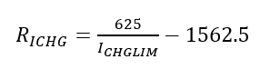
- ICHGLIM is the fast charge current limit in Amps
- RICHG is the resistance to be connected between the ICHG and AVSS pins in Ω
Common values are provided in the following table.
| RICHG resistor value | Nominal charge current limit, ICHGLIM | Error |
|---|---|---|
| 0 (short to AVSS) | 400 mA | ± ICHGACC% |
| 1.5 kΩ | 200 mA | ± (ICHGACC + RICHGACC)% |
| 4.7 kΩ | 100 mA | ± (ICHGACC + RICHGACC)% |
| 11 kΩ | 50 mA | ± (ICHGACC + RICHGACC)% |
| 30 kΩ | 20 mA | ± (ICHGACC + RICHGACC)% |
Battery thermal protection using NTC thermistor (NTC)
Battery thermal protection is implemented in the following two ways.
- Using a battery pack with an integrated NTC thermistor
- Connecting a thermistor between the NTC pin and the AVSS pin
| Parameter | Value | Unit |
|---|---|---|
| Nominal resistance at 25°C | 10 | kΩ |
| Resistance accuracy | 1 | % |
| B25/50 constant | 3380 | Kelvin |
| B25/85 constant | 3434 to 3435 | Kelvin |
| B constant accuracy | 1 | % |
If the thermal protection feature is not used, then a 10 kΩ, ≤20% accuracy resistor should be connected between NTC and AVSS pins.
To provide JEITA compliant thermal protection, the charge current limit and termination voltage are adjusted according to the NTC thermistor measurement.
| Temperature region | Battery temperature | Charging current | Termination voltage |
|---|---|---|---|
| Cold | T < 0°C | 0 (OFF) | NA |
| Cool | 0°C < T < 10°C | IREDUCED | VTERM |
| Nominal | 10°C < T < 45°C | ICHGLIM | VTERM |
| Warm | 45°C < T < 60°C | ICHGLIM | VTERM-VTHIGH_DELTA |
| Hot | T > 60°C | 0 (OFF) | NA |
Charger thermal regulation
Charger error conditions
A CHARGER error condition occurs when one of the following are present:
- A battery short (VBAT to AVSS)
- Battery voltage lower than VBATCHARGEMIN after battery detection due to a fault with the battery
- Trickle charge timeout; see TOUTTRICKLE
- Constant voltage charge/fast charge timeout; see TOUTCHARGE
- Device internal error occurs when CHARGER is self-checking
After an error is detected, CHARGER is disabled, the charging error indication is activated, and the charging indication is deactivated. Error conditions are cleared when VBUS is disconnected and reconnected again.
Charging indication (CHG) and charging error indication (ERR)
The charging indication pin CHG and charging error indication pin ERR sink 5 mA of current when active. They are high impedance when disabled. This is suitable for driving LEDs or connecting to host GPIOs in a weak pull-up configuration.


The charging indication pin, CHG, is active while the battery is charging.
The charging error indication pin, ERR, is activated when an error occurs, see Charger error conditions.
DPPM — Dynamic power-path management
CHARGER manages battery current flow to maintain VINT voltage.
The system load requirements are prioritized over battery charge current when VBUS is connected and the battery is charging. The battery is isolated when VBUS is connected and the battery is fully charged. SYSREG supplies the load unless the load exceeds SYSREG limits. When VBUS is disconnected, CHARGER switches to battery supply.
During charging, if the combined current load ILOAD on VINT (including BUCK input current) and VBAT (ICHG) exceeds the current provided by SYSREG (ILIM), the battery charge current decreases to maintain the VINT voltage. The battery charger reduces the current to maintain the internal voltage: VINT = V(VBAT )+ VDROPOUT_CHARGER. If more current is required, CHARGER enters Supplement mode, switching to provide current from the battery, up to IBATLIM.
If a charge cycle ends and ILOAD exceeds ILIM, CHARGER connects the battery and enters Supplement mode to maintain VINT.
When VBUS and the battery are connected, the maximum supported load is ILIM + IBATLIM.
| VBUS connected | Battery connected | Load | CHARGER | VINT supply | VINT voltage |
|---|---|---|---|---|---|
| Yes | Yes | (ILOAD + ICHGLIM) < ILIM | Charging | VBUS | V(VBUS) |
| Yes | Yes | (ILOAD + ICHGLIM) > ILIM ILOAD < ILIM |
Charging (ICHG reduced) |
VBUS | V(VBAT) + VDROPOUTCHARGER |
| Yes | Yes | ILOAD > ILIM | Supplement mode | VBUS and VBAT | V(VBAT)1 |
| Yes | No | ILOAD < ILIM | N/A | VBUS | V(VBUS) |
| No | Yes | ILOAD ≤ IBATLIM | N/A | VBAT | V(VBAT)1 |
1CHARGER has a resistance of RONCHARGER between VBAT and VINT. The voltage drop from VBAT to VINT is IBAT x RONCHARGER, where IBAT is the current being drawn from the battery.
Electrical specification
| Symbol | Description | Min. | Typ. | Max. | Unit |
|---|---|---|---|---|---|
| ICHGACC | Fast Charge current accuracy for ICHG ≥ 50 mA, 0.1% accuracy external resistor | ±10 | % | ||
| ICHGACC | Fast Charge current accuracy for ICHG < 50 mA, 0.1% accuracy external resistor | ±15 | % | ||
| VTERM0 | Standard termination voltage, VTERMSET = LOW | - | 4.1 | - | V |
| VTERM1 | Standard termination voltage, VTERMSET = HIGH | - | 4.2 | - | V |
| VTERM0 | High termination voltage, VTERMSET = LOW | - | 4.25 | - | V |
| VTERM1 | High termination voltage, VTERMSET = HIGH | - | 4.35 | - | V |
| VTERMACC0 |
Termination voltage accuracy |
-1 | - | +1 | % |
| VTHIGH_DELTA | VTERM voltage reduction at high temperature | 100 | mV | ||
| ITERM | Termination current | 8 | 10 | 12 | % of ICHG |
| ITRICKLE | Trickle charge current | 10 | % of ICHG | ||
| IREDUCED | Fast charge current when device junction temperature is above THIGH or battery temperature is below TNTCCOOL | - | 50 | - | % of ICHG |
| THIGH | High temperature threshold | - | 100 | - | °C |
| THIGHHYST | High temperature hysteresis | - | 10 | - | °C |
| VTRICKLE_FAST | Trickle to Fast Charge threshold | - | 2.9 | - | V |
| VRECHARGE | Recharge threshold | - | 97 | - | % of VTERM |
| VBATCHARGEMIN | Minimum voltage during charge | - | 2.1 | - | V |
| TOUTTRICKLE | Trickle charging timeout | - | 10 | - | min |
| TOUTCHARGE | Timeout for Fast charging and constant current charging | - | 7 | - | hour |
| VDROPOUT_CHARGER | VINT - VBAT voltage for charging | - | 50 | - | mV |
| VDROPOUT_VBUS | Minimum VBUS - VBAT voltage for charging | - | 140 | - | mV |
| TREDETECT | Period between detection events | - | 500 | - | ms |
| IBATLIM | Output current limit from battery in discharge | - | 660 | - | mA |
| RONCHARGER | CHARGER resistance between VBAT and VINT in Discharge, VBAT = 3.7 V | - | 130 | 230 | mΩ |
| VBATPOR | Power-on reset release voltage for VBAT | - | 2.7 | - | V |
| VBATBOR | Brownout reset trigger voltage for VBAT 1 | - | 2.5 | - | V |
| ISINK | DC current (CHG and ERR) | - | 5 | - | mA |
| TNTCCOLD | JEITA cold temperature threshold (Thermistor: 10 kΩ, B25/50=3380 K) | - | 0 | - | °C |
| RNTCCOLD_FALLING | Resistance threshold from cool to cold | 25.53 | 27.28 | 29.13 | kΩ |
| RNTCCOLD_RISING | Resistance threshold from cold to cool | 23.10 | 26.00 | 28.20 | kΩ |
| TNTCCOOL | JEITA cool temperature threshold (Thermistor: 10 kΩ, B25/50=3380 K) | - | 10 | - | °C |
| RNTCCOOL_FALLING | Resistance threshold from nom. to cool | 16.80 | 18.00 | 19.20 | kΩ |
| RNTCCOOL_RISING | Resistance threshold from cool to nom. | 15.50 | 17.10 | 18.60 | kΩ |
| TNTCWARM | JEITA warm temperature threshold (Thermistor: 10 kΩ, B25/50=3380 K) | - | 45 | - | °C |
| RNTCWARM_FALLING | Resistance threshold from warm to nom. | 4.86 | 5.13 | 5.43 | kΩ |
| RNTCWARM_RISING | Resistance threshold from nom. to warm | 4.68 | 4.92 | 5.17 | kΩ |
| TNTCHOT | JEITA hot temperature threshold (Thermistor: 10 kΩ, B25/50=3380 K) | - | 60 | - | °C |
| RNTCHOT_FALLING | Resistance threshold from hot to warm | 3.04 | 3.19 | 3.35 | kΩ |
| RNTCHOT_RISING | Resistance threshold from warm to hot | 2.90 | 3.02 | 3.15 | kΩ |
1Device enters BOR only if (V(VBUS) < VBUSBOR) AND (V(VBAT) < VBATBOR).
Electrical characteristics
The following graphs show CHARGER electrical characteristics.


