Thread Border Router serves as a gateway between the Internet and the Thread network. There are two ways of connecting the Thread Border Router to the Internet. The first one uses the standard Ethernet cable with an RJ-45 plug, while the other one uses a built-in Wi-Fi module.
The Border Router is intended for development purposes, to make it easy for developers to connect their Thread network to the Internet in the development phase. It also supports the Thread native commissioning procedure utilizing NFC to initiate the process.
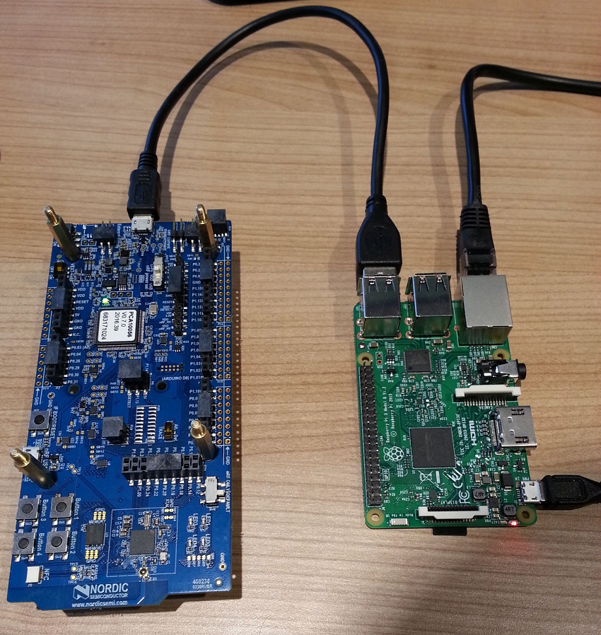
The Border Router consists of Raspberry Pi 3 B, NXP Semiconductors' NFC reader shield, and Nordic’s nRF52840 Development Kit. The NXP Semiconductors' NFC reader shield is an optional element required for Thread native commissioning. However, the shield is not necessary to connect a Thread network to the Internet.
nRF52840 Development Kit acts as a connectivity chip running the Network Co-Processor (NCP) application. It communicates with Raspberry Pi using the Spinel protocol. Raspberry Pi firmware is based on OpenWRT (distribution #cb9d252) and contains several deamons for controlling the NCP and the NFC reader shield, such as wpantund on GitHub and NFC commissioning deamon.
For your convenience, this SDK provides pre-built, ready-to-use binary images for both nRF52840 and Raspberry Pi. The binary image intended for Border Router is distributed under license inherited from OpenWRT project (OpenWRT_LICENSE.txt), with limitations imposed by license inherited from NXP’s EXPLORE_NFC_WW (NXP_EXPLORE-NFC-WW_LICENSE.pdf). EXPLORE_NFC_WW license applies if a user uses a Border Router feature to natively commission nodes using NFC. Licenses can be found in the package containing the Border Router binary image. For corresponding source code and build system, refer to README.md.
Required hardware
- Raspberry Pi 3 B
- nRF52840 Development Kit
- 1 GB (or larger) microSD card with SD card adapter
- microUSB power supply for Raspberry Pi 3 B
- microUSB to USB cable for connecting the nRF52840 Development Kit to the Raspberry Pi
- Computer running the Windows operating system with SD card slot or SD/microSD USB adapter
- Note
- Windows is used in this procedure but Linux and macOS operating systems are also supported.
- Optional: EXPLORE-NFC-WW Raspberry Pi shield - required for running the Thread NFC MeshCoP Example.
- Optional: Additional nRF52840 Development Kit for Border Router testing - a client that can connect to the Internet using the Border Router.
Required software
- Win32 Disk Imager
- nrfjprog – available in nRF5x-Command-Line-Tools-Win32 from the nRF52840 product website
- Terminal client with serial connection support, such as PuTTy
- Border Router Raspberry Pi image available from nRF5 SDK for Thread web page "nRF5 SDK for Thread v0.11.0 web page" -
RaspPi_Thread_Border_Router_Demo_v0.11.0-1.alpha.img - NCP example located in
<InstallFolder>\examples\thread\experimental\ncp - CLI example located in
<InstallFolder>\examples\thread\experimental\cli
Setup procedure
Complete the following steps to set up the Border Router solution:
Flashing the Raspberry Pi image to the microSD card
- Install microSD card in your computer and start the Win32 Disk Imager.
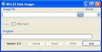 Win32 Disk Imager
 - In the Image File field, point to
RaspPi_Thread_Border_Router_Demo_v0.11.0-1.alpha.img. - In the Device field, select a device that corresponds to the microSD memory card that you connected to the computer.
- Warning
- If you choose an incorrect device, you may overwrite a partition on your computer or another device. Verify your choice by checking the letter mapped to the microSD card in My Computer.
- Click Write.
- After the image has been flashed, safely remove the microSD card from your computer. To do this, right-click the USB symbol in the taskbar and click Eject on the volume that represents the SD card.
- Insert the microSD card into your Raspberry Pi.
Flashing the Network Co-Processor to the nRF52480 Development Kit
- Connect the nRF52840 Development Kit to the computer and power it on.
- Open the terminal (e.g. by pressing Windows Key + R and running
cmd). - Run the following command: nrfjprog --chiperase --family NRF52 --program <InstallFolder>/examples/thread/experimental/ncp/uart/hex/nrf52840_xxaa.hex
- Note
- You can use the USB CDC version of the NCP example as well. Keep in mind though, that the native nRF USB port must be used in this case.
Starting the Border Router
- Connect the nRF52840 Development Kit to the Raspberry Pi using the microUSB – USB cable.
- Connect the Raspberry Pi through an Ethernet cable or WiFi to your switch/router that provides IPv4 or IPv6 connectivity with the DHCP or DHCPv6 service respectively.
- Power on the nRF52840.
- Connect the microUSB power supply to the Raspberry Pi. The Border Router will start booting. Depending on your microSD card speed, the Border Router should be fully operational within two minutes.
 Starting the Border Router
Thread Settings:
The following are the default settings of the Border Router:
To customize the Thread settings, you must connect to the Border Router using SSH. It is recommended to set a password, which can be done using the passwd command after logging in through SSH, or in the LuCI configuration panel.
Because the Border Router received its IPv4 address dynamically using DHCPv4, you must log in to the router and check its address. Alternatively, you can use scanning software like Advanced IP Scanner. When the IPv4 address is known to you, open an Internet browser and go to this address. The LuCI configuration panel opens. The default logging credentials are: id: "root" and empty password. Change the password to a non-empty value.
Log in to the router using SSH. Vim and nano text editors are available on the Border Router. To change the settings, edit the /etc/config/thread_border_router file. The following lines can be found at the top of the file:
Edit these variables to customize the Thread configuration.
Connectivity:
NAT64 technology is enabled by default. It is used to enable communication between the IPv6-only Thread network with pure IPv4 LAN network that the Border Router connects to, as is the case in most applications. In that way, Thread nodes are able to connect to IPv4 cloud services. Thread devices will receive a NAT64-prefix and use it to create their own Unique Local Address.
The other connectivity option, which is also enabled by default, is support for the native IPv6 connection. It uses built-in DHCPv6 client on the Border Router which is able to receive prefixes from the Ethernet interface. If the received prefix is shorter than 63 bits, the 64-bit long subnet prefix is created and forwarded to the Thread network. In such situation, devices create one more address based on the forwarded prefix, which, unlike in a pure NAT64 solution, allows them to be reached from the Internet.
- Note
- When dealing with native IPv6 connectivity, make sure you use the DHCPv6 service, and not the popular Stateless Address Autoconfiguration (SLAAC) tool. This autoconfig tool will only provide a 64-bit long prefix that is not sufficient to delegate a new 64-bit long prefix for the Thread network.
Support for Domain Name System (DNS) resolution is also available. This mechanism is used to translate a host name into a corresponding IP address. It can be used either for translating a domain name into its native IPv6 or for obtaining its IPv4 address and returning IPv6 translated with the DNS64 mechanism.
Testing
To test the Border Router, you can use another node with command line interface (CLI) and ping the Google DNS server 8.8.8.8.
- Flash another nRF52840 Development Kit with nrfjprog, as described in Thread CLI Example. This time, use the following command: nrfjprog --chiperase --family NRF52 --program <InstallFolder>/examples/thread/experimental/cli/uart/hex/nrf52840_xxaa.hex --reset
- Start a terminal emulator like PuTTY and connect to the used COM port with the following UART settings:
- Baud rate: 115.200
- 8 data bits
- 1 stop bit
- No parity
- HW flow control: None
- PuTTy must be configured in two steps. First, in the Session tab, set the the Serial line, Speed, and Connection Type values.
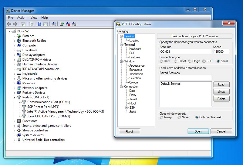 First step of PuTTY configuration
 - Then, in the Connection -> Serial tab, set the remaining parameters, i.e. Data bits, Stop Bits, and Flow control.
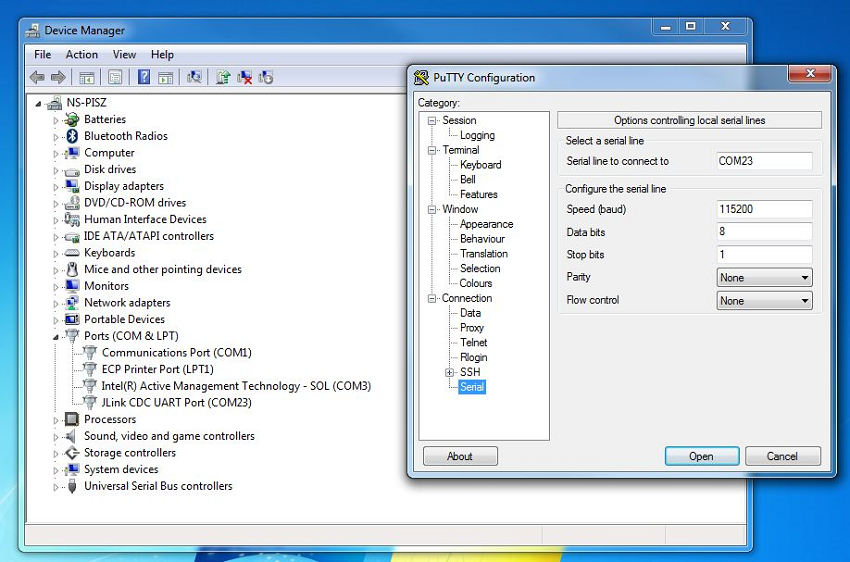 Second step of PuTTy configuration
- After the console window appears, press Enter. If the prompt mark ">" appears, the serial connection has been established. When a command is executed successfully, ">Done" is reported.
- Run the following commands: panid 0xabcdifconfig upthread startstateping fd00:0064:0123:4567::0808:0808
- Note
- 0808:0808 is in fact the Google DNS server address "8.8.8.8" in hex representation. In that way, you can reach any IPv4 cloud by replacing last 32 bits of an IPv6 address with a correctly encoded IPv4 address.
- After running the command, you should receive the following result: 16 bytes from fd00:64:123:4567:0:0:808:808: icmp_seq=5 hlim=39 time=111ms
- Obtain the addresses of the connected node by typing
ipaddr:If IPv6 connectivity is present, the device will obtain the global IPv6 address starting with a> ipaddr2001:db8:dead:beef:98ba:8f31:fc05:6919fdff:cafe:cafe:cafe:274d:4873:f46:a6acfdde:ad00:beef:0:bebd:ae25:a6c7:a0b5fdde:ad00:beef:0:0:ff:fe00:b001fe80:0:0:0:a4aa:fd14:d403:89d6fdde:ad00:beef:0:9ae1:534:a3c4:49f8Done2000::/3prefix, in this example 2001:db8:dead:beef:98ba:8f31:fc05:6919. This address can be used to reach the node from any IPv6-connected device. The simplest test is to ping this address from a computer connected to the IPv6 network. - You can use DNS to resolve the native IPv6 address of the given host name in the following way: If the host does not have IPv6 connectivity, a Thread device may still connect with a IPv4 cloud utilizing the NAT64 and DNS64 protocols. To obtain a a translated IPv6 address, you must specify the DNS resolver fd00:0064:0123:4567::1 which is running on the Thread Border Router, as shown below:> dns resolve ipv6.google.com> DNS response for ipv6.google.com - [2a00:1450:401b:802:0:0:0:200e] TTL: 299> ping 2a00:1450:401b:802:0:0:0:200e> 8 bytes from 2a00:1450:401b:802:0:0:0:200e: icmp_seq=2 hlim=55 time=42msError 25 indicates that there is no IPv6 address returned as the ipv4.google.com does not have any.> dns resolve ipv4.google.com> DNS response for ipv4.google.com - Error 25> dns resolve ipv4.google.com fd00:0064:0123:4567::1> DNS response for ipv4.google.com - [fd00:64:123:4567:0:0:acd9:14ae] TTL: 300> ping fd00:64:123:4567:0:0:acd9:14ae> 8 bytes from fd00:64:123:4567:0:0:acd9:14ae: icmp_seq=3 hlim=55 time=42ms
Thread Border Router Wi-Fi usage and configuration
In a typical use case, it is assumed that no additional communication interface is present. In such scenario, Thread Border Router starts in Access Point mode, advertising its own Wi-Fi network called "Nordic Thread Border Router". A user connects to this network and chooses a local Wi-Fi network for the Thread Border Router to connect to.
Next, the network advertised by the Thread Border Router becomes unavailable. The switch from Access Point mode to Station mode occurs and the connectivity between the Thread Network and the Internet through the local Wi-Fi is maintained.
The behavior of the Router after the reboot can be configured using a jumper or a configuration file. Details are presented in Configuring Wi-Fi behavior after reboot.
Configuring Wi-Fi behavior after reboot
The Border Router will by default store the previous network configuration after a reboot. You can change this behavior either by using a jumper on the Raspberry Pi board or by editing a configuration file:
Using a jumper:
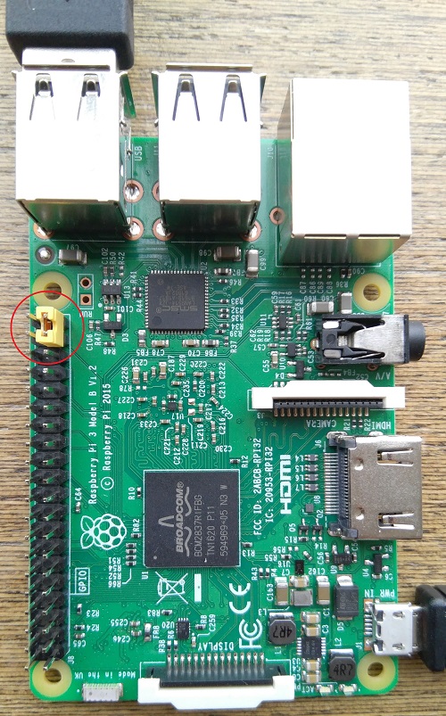
You can configure a jumper in order to reset the Wi-Fi configuration after each reboot:
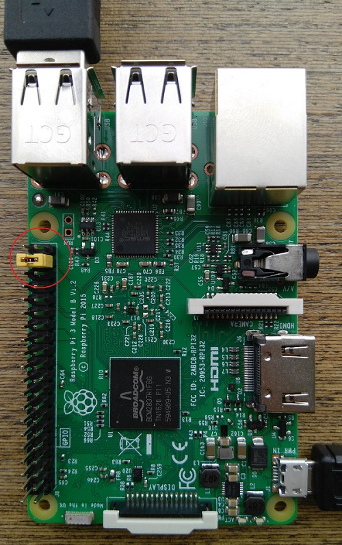
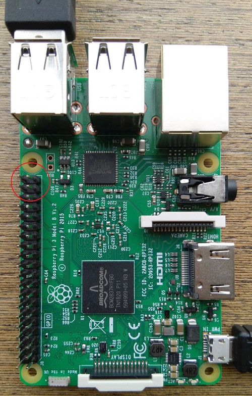
To maintatin the configuration after a reboot, GPIO26 must be connected to GND or simply left disconnected:
Using a configuration file: Edit the file /boot/wifi_config.txt. Set the erase_wifi_configuration property to 1 to revert the wireless settings to the default Access Point configuration after every reboot. The default setting (erase_wifi_configuration=0) will store the previous network configuration.
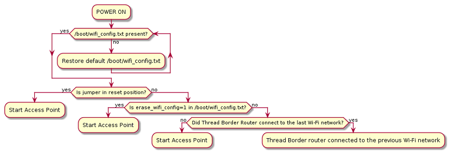
Wi-Fi init procedure
The following flowchart presents the Wi-Fi initialization procedure:
When the Access Point is enabled, the following steps are required to connect the Thread Border Router to the specified Wi-Fi network in a client mode.
- Connect to the Nordic Thread Border Router Wi-Fi network: SSID: Nordic Thread Border RouterPassword: nordicBR
- Open the browser and type the
192.168.2.1address:Username: rootPassword: (blank) - Press Login:
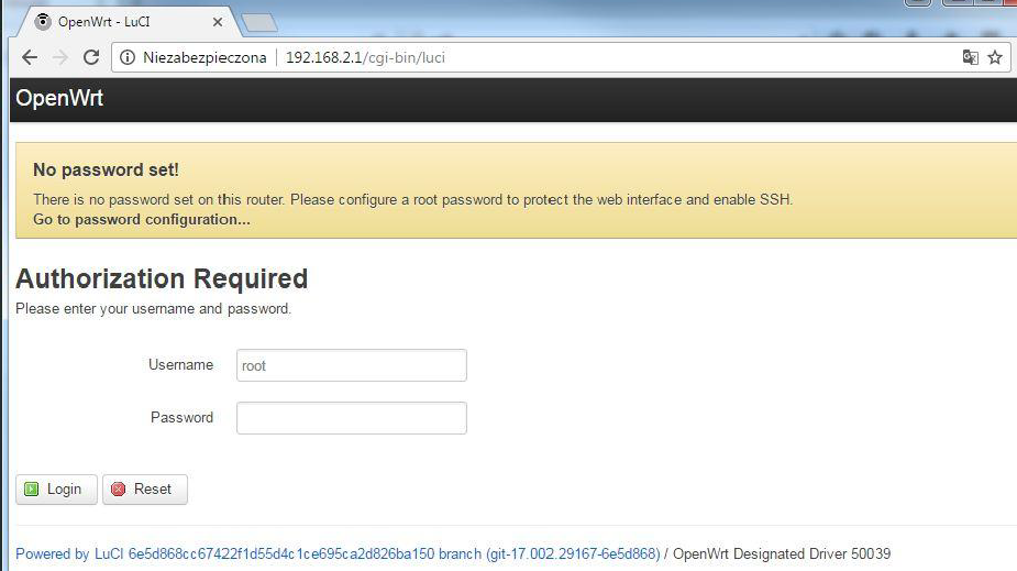 Log on to the Router
 - Click Network -> Wireless:
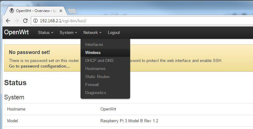
- Click Scan:
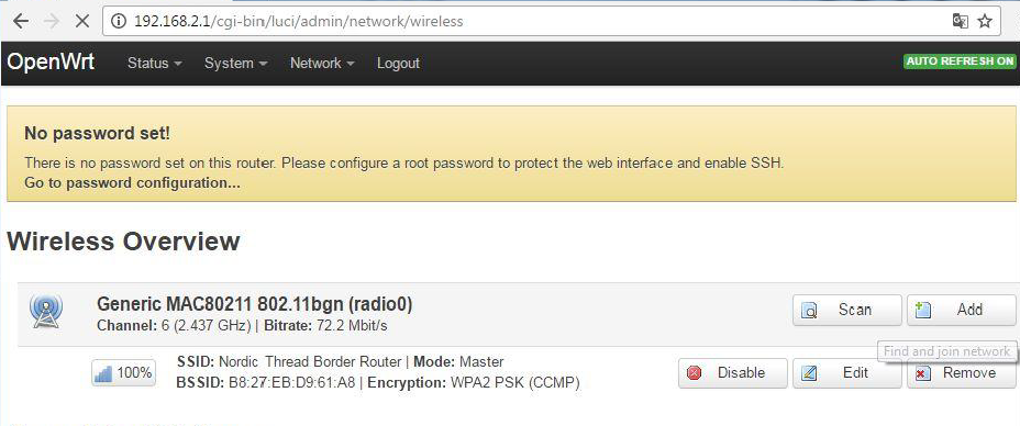
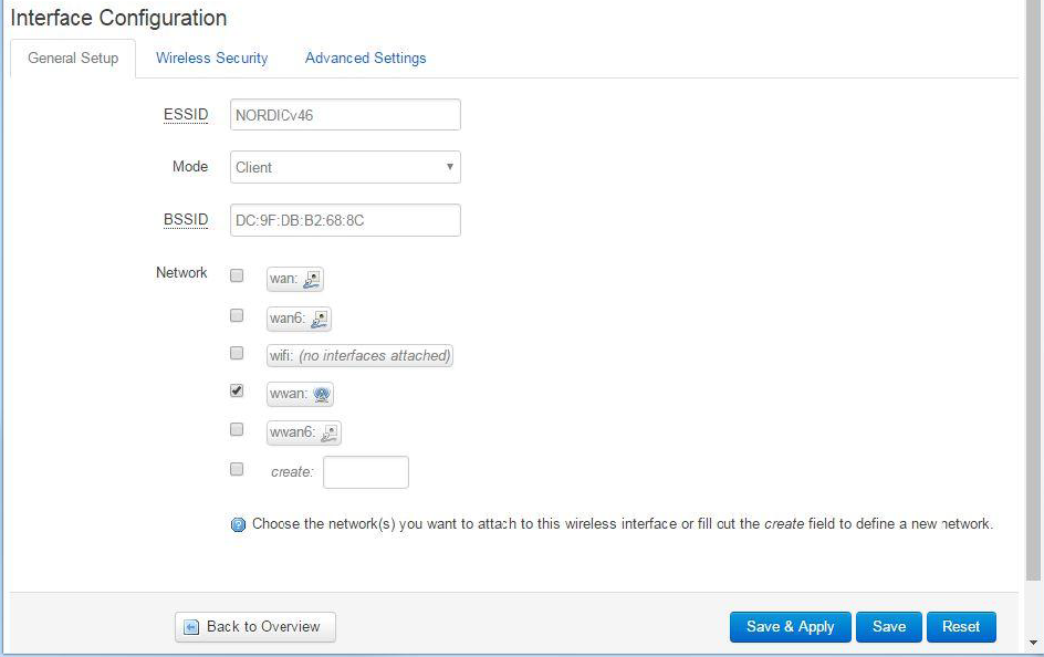
- Select the network to which you want to connect. Click Join Network:
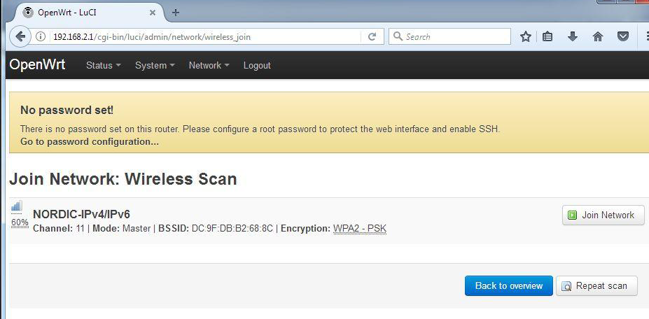
- Type in the WPA password to the selected network and press Submit:
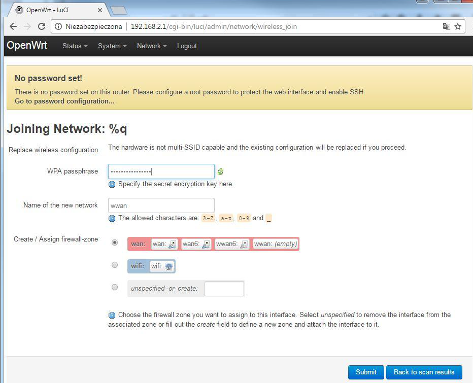
- Scroll down to the bottom of the page and click Save & Apply:
From now on, the Access Point provided by the Thread Border Router will no longer be available. The configuration panel will stop responding as well. Thread Border Router is now connected to the selected Network and will obtain its IPv4 and IPv6 addresses using DHCP and DHCPv6 respectively.
Running MQTT-SN Gateway on Thread Border Router
The MQTT-SN Gateway used in the Thread MQTT-SN Example can be run on the Thread Border Router. To do that, MQTT-SN Gateway must be enabled in the /etc/config/thread_border_router file. The paho_mqtt_sn_gateway_enable flag must be set to true.
With this option enabled, MQTT-SN Gateway starts automatically once you reboot the Raspberry Pi. The gateway has already been configured to work correctly with the Thread MQTT-SN Example.
Configuration of the MQTT Broker
The configuration file for the Paho MQTT-SN Gateway is located in /etc/paho-mqtt-sn-gateway.conf. By default, the IPv4 address of the Eclipse IoT MQTT Broker is used. You may want to use another MQTT Broker. To do that, modify the BrokerName and BrokerPortNo variables in the configuration file.
Note that you need to type the IPv4 address of the MQTT Broker. The host name representation is currently not supported.