Introduction
Persistent data storage is a useful tool for Bluetooth low energy applications that need to store exchanged information. For example, when a bonded peer configuration needs to be cached to store the bond identification, GATT Server configuration, and/or GATT Server attribute handles, persistent data storage is used.
The Persistent Storage Manager has a generic API (Persistent Storage Interface) that is used by the SDK modules for common storage access. A generic API means that SDK modules can be reused directly on other platforms. All modules using the Persistent Storage Manager are decoupled from accessing the nRF51822 flash directly, making the SDK modules easier to reuse. For example, the Device Manager can be used on processors other than nRF51822 by implementing a storage module according to the Persistent Storage Manager API for the targeted platform.
The application interface of this module is as defined in the header and should not be altered in order to preserve the other SDK modules. The interface implementation is expected to vary based on the storage solution identified for the system. Therefore, pstorage.h defines the application interface, while pstorage_platform.h is a use case and system specific file that can contain defines and routines needed for a specific implementation of the identified interface. The source file, pstorage.c shall implement the needed APIs. SDK examples include implementation of the interface using the SoftDevice APIs for flash access on the chip.
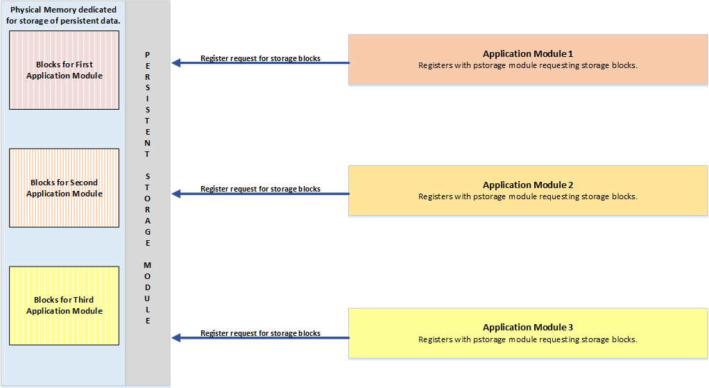
Multiple SDK modules and the application itself may be required to store data, with each module having its own data size requirements. Therefore, this module allows registering various block size and block count, each with a separate event handler that is notified of the flash access results.
Memory layout
The pstorage_platform.h file contains the information defining where the application data is stored in flash. Generally, the rules are as follows:
- If no bootloader is present on the device, the application data is stored at the top of the flash memory. The 512 kB flash memory has a range of 0x00000000 to 0x00080000 in the memory map. The last page (addresses 0x7F000 to 0x7FFFF) is the internal pstorage swap page. If there are two pages reserved for the application data, it is two pages below the pstorage swap page in the memory map (addresses 7D000 to 7EFFF), see the pstorage_platform.h defines (PSTORAGE_NUM_OF_PAGES constant). When there is no bootloader and the value of PSTORAGE_NUM_OF_PAGES is 2, then the application data is stored at 0x7D000. The memory content can be read in the command prompt by using:
nrfjprog –memrd 0x0007D000 –n 8192
- If the device manager is used and is initialized, it will use one flash page. If the device manager is initialized before calling pstorage_register for your application data, the device manager will use the first page (starting with address 0x7D000) and the application data will be stored in the second page (starting with address 0x7E000). For details see the figure below.
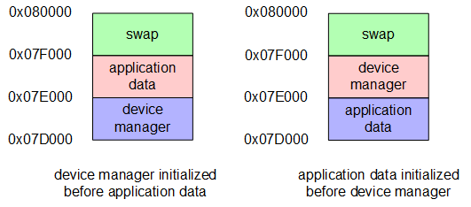
- When a bootloader is present, it is located at the top of the flash memory with the application data it in the memory map, as Memory layout. For the bootloader in the SDK release, its start address is 0x7B000. To check the location yourself, you can read out the bootloader start address from UICR with:
nrfjprog –memrd 0x10001014 –n 4
If the start address of the bootloader is 0x7B000, then the swap page start address is at 0x7B000-0x1000=0x7A000 and the two pages of application data are located from 0x7A000-0x2000=0x78000 to 0x79FFF. The memory content of the two application data pages can be read with:
nrfjprog –memrd 0x00078000 –n 8192
Application Interface Overview
Any SDK or application component that is required to store its data registers with the module using the pstorage_register, will at the time of registration request the number of blocks of storage needed. The interface is designed to be asynchronous and the application is expected to register a callback to know the result of a storage access operation. Identified storage access operations include load, store, and clear. Once the application is successfully registered, the application is assigned a handle for all future operations needed for accessing these storage blocks. This handle is abstracted by pstorage_handle_t (in the platform-specific header file).
- Warning
- Before accessing any of the module APIs, the module shall be initialized using the Initialization. This initialization should be performed once.
- Note
- To implement the interface included in the example, the SoftDevice should be enabled and the scheduler (if used) should be initialized prior to initializing this module.
The application does not have to remember a handle or an identifier for each block. Instead, it needs to remember only one identifier for all the blocks. When a reference to a specific block for flash access is required, pstorage_block_identifier_get API shall be used to get a block specific handle. The base handle and block number starting from 0 are provided as input to the API.
As mentioned earlier, an asynchronous interface is defined for storage access since storing data and clearing data can take time. However, data that is to be stored is not copied by the implementation included in the SDK. Therefore, the data source provided for the store operation using the Store Data API expects resident memory. This means that the memory the data source for this API points to should not be reused or freed unless the client is notified by the asynchronous notification callback registered with the module upon completion of a store operation.
Initialization
The storage module must be initialized before using any other API of the module.
Registration
A module that requires storage must register with the storage module in order to allocate storage blocks for data. The application must register the asynchronous event notification handler, number of blocks, and block size which should be in range of PSTORAGE_MIN_BLOCK_SIZE and PSTORAGE_MAX_BLOCK_SIZE. A reference handle is given to the application once registration is successful and is remembered by the application to reference the storage blocks.
- Note
- The application is provided here with a single handle for all blocks and a dedicated handle for each block. This saves the application from having to remember too many handles. The handle provided to the application is referred to as the base handle for the blocks allocated. The application shall use pstorage_block_identifier_get to acquire a specific block reference.
Get Block Identifier
This API provides a specific block reference to the application in allocated blocks. Allocated blocks are identified by the base block identifier provided at the time of registration. Block offset is indexed starting from zero to (number of blocks allocated - 1).
This API shall be called before a load or store operation to a specific block.
Load Data
This API is used to read data from a storage block. It is permitted to read a part of the block using the offset field. The application should ensure that the destination has enough memory to copy data from the storage block to the destination pointer provided in the API.
- Note
- The block size and offset in load and store should be a multiple of word size (4 bytes). To get the block specific identifier Get Block Identifier API shall be used before this API.
- Note
- The SDK implementation requires the offset and size to be a multiple of word size (4 bytes) and will not generate a success or failure event. The API return value determines the result of this operation.
Store Data
This API is used to write data to a storage block. It is permitted to write only a part of the block using the offset field. The application cannot free or reuse the memory that is the source of data until this operation is complete. The event notified using a registered callback will indicate when this operation is complete. The event result indicates whether the operation was successful or not.
- Note
- Block size and offset in load and store should be a multiple of word size (4 bytes). To get a specific block identifier, Get Block Identifier API should be used before this API.
- Note
- Flash memory is unreliable when writing to a block already containing data. A clear operation is needed because the SDK implementation does not clear the blocks before writing to them. The application, not the storage module, must perform a clear operation before new data is written to the block.
Update Data
This API is used to update data in storage blocks. The application cannot free or reuse the memory that is the source of data until this operation is complete. The event notified using a registered callback will indicate when this operation is complete. The event result indicates whether the operation was successful or not.
Clear Data
This API is used to clear data in storage blocks. The event notified using a registered callback will indicate when this operation is complete. The event result indicates whether the operation was successful or not.
The size requested to be erased has to be equal or a multiple of the block size.
Get Status
The Persistent Storage Manager uses the pstorage_access_status_get API to communicate to an application how many storage access operations are pending. This is particularly useful when you want to enter power off mode or want to enter a radio intense operation, but before doing so, want to ensure that the storage operations are complete.
Raw Mode
Certain use cases require complete control of the entire flash region and do not have typical storage requirements. The storage module then provisions for one application to be registered with it in 'raw' mode. In raw mode, the application is responsible for conceptualizing the flash region as blocks and their management. Dedicated APIs, register, store, and clear are provided to distinguish raw mode from the normal mode. Raw mode APIs have a similar signature to the normal mode.
Because this is not a typical use case, raw mode is included for only a few applications like the DFU, and by default is disabled. It is included only if PSTORAGE_RAW_MODE_ENABLE is defined in the pstorage_platform.h header.
Specifics and limitations of the SDK implementation
Additional requirements and a few limitations exist when implementing the example included. Some have already been mentioned but the following is a summarized list with more detailed information.
General:
- The SoftDevice and scheduler must be initialized first before initializing the Persistent Storage Module. Modules that use this storage module shall then be initialized after the storage module.
- Block size and offset in load, store, and update shall be a multiple of word size (4 bytes).
- Module APIs are not thread-safe or re-entrant.
- The application is expected to ensure that when a System OFF is issued, flash access is not ongoing or queued with the module.
- Power off is not handled by the module. Therefore, a power off when a flash operation is on-going or pending results in a loss of data.
- Registering for system events and passing them on to the pstorage module using the pstorage_sys_event_handler is mandatory for the module to function as expected. The code snippet below demonstrates what an application needs to do. /**@brief Function for dispatching a system event to interested modules.@details This function is called from the System event interrupt handler after a systemevent has been received.@param[in] sys_evt System stack event.*/static void sys_evt_dispatch(uint32_t sys_evt){pstorage_sys_event_handler(sys_evt);}/**@brief BLE stack initialization.@details Initializes the SoftDevice and the stack event interrupt.*/static void ble_ant_stack_init(void){// Initialize SoftDevice// Subscribe for BLE events.uint32_t err_code = softdevice_ble_evt_handler_set(ble_evt_dispatch);APP_ERROR_CHECK(err_code);// Register with the SoftDevice handler module for System events.err_code = softdevice_sys_evt_handler_set(sys_evt_dispatch);APP_ERROR_CHECK(err_code);}
Registration:
- Registration of a new module shall use a block size which is a multiple of word size (4 bytes).
Store:
- Writing data to blocks that already have stored data is unreliable. The application must clear the blocks before writing new data to them.
- No intermediate copy is made of the source data that will be stored in flash. The application cannot free or reuse the memory that is the data source until this operation is complete. The event notification callback notifies when this operation is complete.
Update:
- When using the update routine, the Persistent Storage Manager will use a swap area to conserve the blocks not affected. The data page is backed up in the swap area before it is erased, then the non affected blocks are copied back before the updated block is stored. It is not possible to update multiple blocks in one API call. The module detects if backing up the page is needed or not and optimizes accordingly.
- No intermediate copy is made of the source data that is to be stored in flash. The application cannot free or reuse the memory that is the data source until this operation is complete. The event notification callback notifies on the completion of this operation.
- The update operation is time intensive, so developer discretion is advised. The application should be tolerant to this.
Clear:
- When using the clear operation the Persistent Storage Manager will use a swap area to conserve the blocks not affected. The data page is backed up in the swap area, then erased, and the non affected blocks are copied back.
- The size parameter must be equal to or a multiple of the block size expressed in number of bytes.
- Clear operation is time intensive, so developer discretion is advised. The application should be tolerant to this.
Technical implementation details
The figure below illustrates the top level state transition diagram of the Persistent Storage Manager.
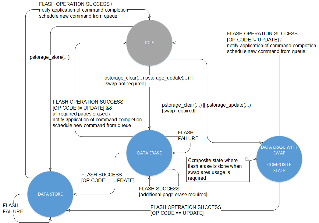
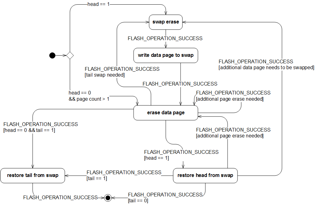
The figure below illustrates the internal state transition diagram of the DATA ERASE WITH SWAP composite state.
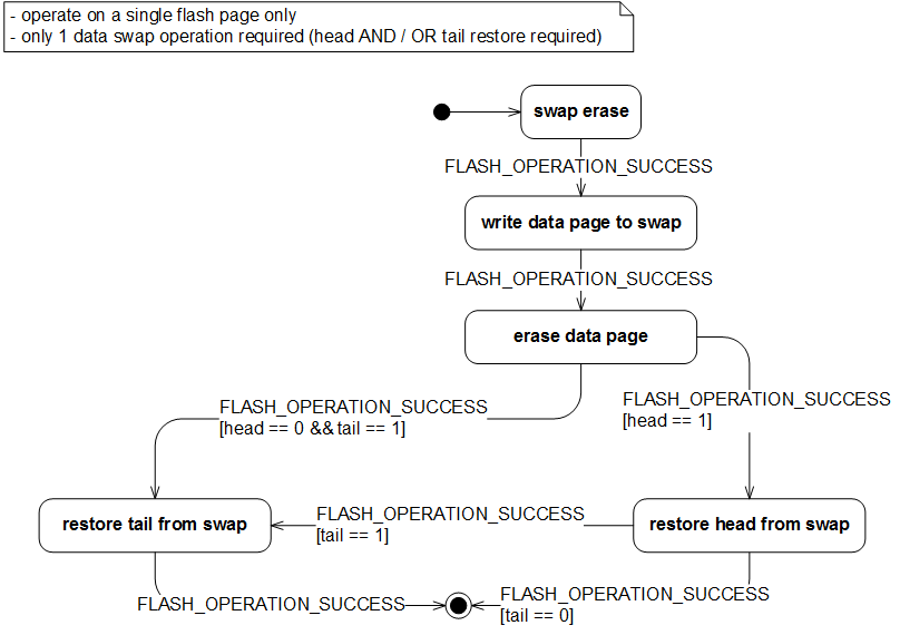
The figure below illustrates the internal state transition diagram of the DATA ERASE WITH SWAP composite state when executing a use case which operates only within 1 flash page.
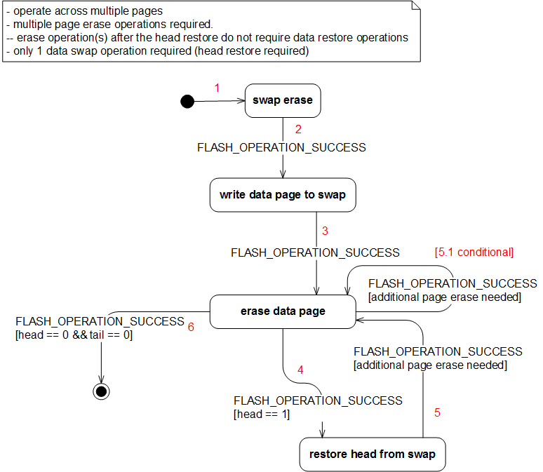
The figure below illustrates the internal state transition diagram of the DATA ERASE WITH SWAP composite state when executing a use case which operates across multiple pages and only head restore is required.
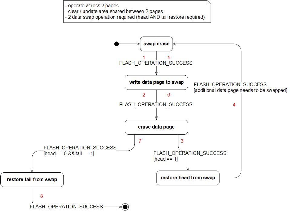
The figure below illustrates the internal state transition diagram of the DATA ERASE WITH SWAP composite state when executing use case which operates across 2 pages and both head and tail restore is required.
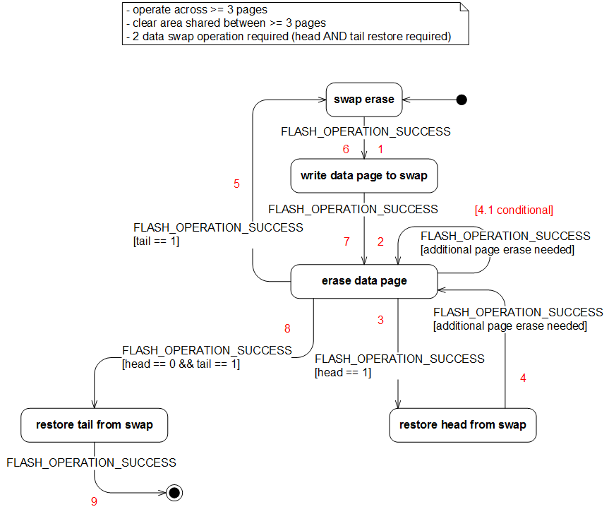
The figure below illustrates the internal state transition diagram of the DATA ERASE WITH SWAP composite state when executing a use case which operates across => 3 pages and both the head and tail restore is required.
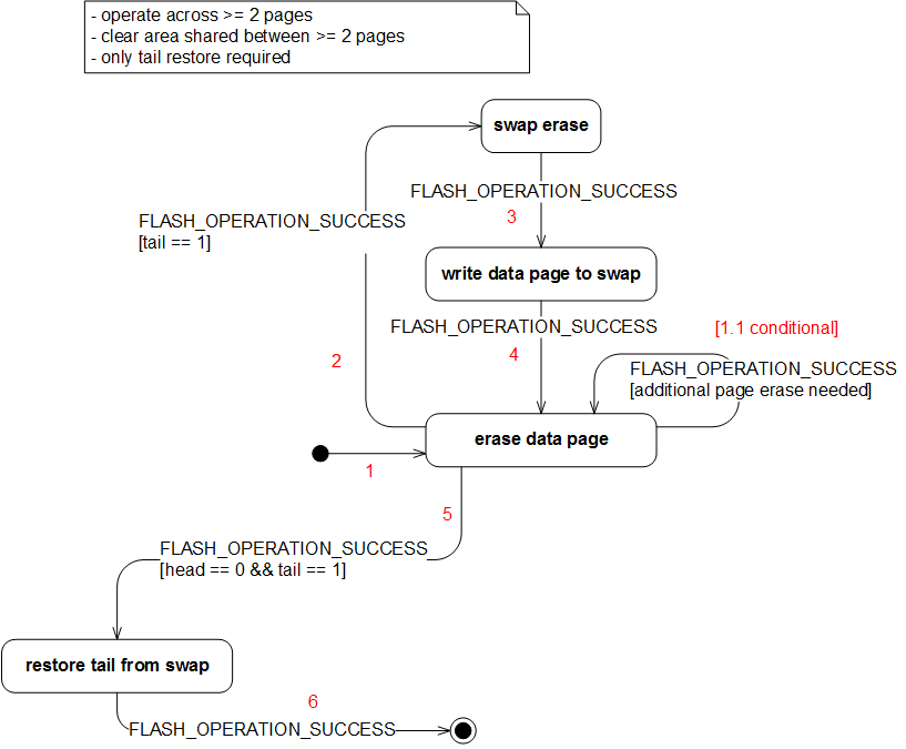
The figure below illustrates the internal state transition diagram of the DATA ERASE WITH SWAP composite state when executing a use case which operates across => 2 pages and the tail restore is required.
