The Bootloader module provides functions to implement a stand-alone bootloader that can bootstrap an application. This bootloader can be extended to provide cryptography functions, DFU support, or custom functionality.
In the most basic form, the bootloader will only start the application that is present at a specific memory address. This behavior is the same as not using a bootloader, so there is no real use case to implement such a basic bootloader. However, you can extend the bootloader with a custom initialization, for example. Another possible use case is that you might want to use the bootloader to switch between several applications that are installed on the device, for example depending on which button is pressed while the device starts.
In your bootloader code, call nrf_bootloader_init to initialize the bootloader. This function internally calls nrf_bootloader_user_init, a function that you can override in your implementation to add custom functionality to the initialization. If you are using nrf_dfu to create a bootloader with DFU functionality, the initialization function also calls nrf_dfu_init.
After initialization, your bootloader code should call nrf_bootloader_app_start to start an application at a given memory address.
Programming the bootloader
During system startup, the Master Boot Record (MBR) is responsible for starting the bootloader, if a bootloader is installed. To do this, the MBR must know the start address of the bootloader. This start address is defined in UICR.BOOTLOADERADDR, which is located at address 0x10001014 (see NRF_UICR_BOOTLOADER_START_ADDRESS). Therefore, you must set UICR.BOOTLOADERADDR to the correct value when you program the bootloader.
Programming the bootloader requires the following steps:
- Erase the device.
- Program the SoftDevice. See Programming SoftDevices for instructions.
- Compile the bootloader.
- Program the bootloader and write to UICR.BOOTLOADERADDR. See the following sections for instructions for Keil, IAR, and nrfjprog directly (if you are using GCC).
Using Keil
You cannot write to UICR.BOOTLOADERADDR when using the default J-Link target driver in Keil. Therefore, you must configure Keil to use an external tool, nrfjprog.exe. To do so, select Project > Options for Target 'xxx' and configure nrfjprog.exe as the tool for flash programming. nrfjprog.exe is installed with the nRF5 MDK and must be in the Windows system path. The following screenshot shows the required settings for nrfjprog.exe (for nRF51 Series devices, change "NRF52" to "NRF51"):
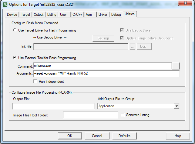
After configuring the flash command, program the bootloader as you would do with a normal application. If several J-Link emulators are connected, select the one that contains the nRF5 IC that you want to flash.
Using IAR
You cannot write to UICR.BOOTLOADERADDR when using the default J-Link target driver in IAR. Therefore, you must set up nrfjprog.exe as an external tool. To do so, select Tools > Configure Tools. nrfjprog.exe is installed with the nRF5 MDK and must be in the Windows system path. The following screenshot shows the settings for nrfjprog.exe:
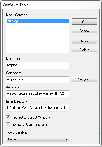
For nRF51 Series devices, change "NRF52" to "NRF51". You must also change "app.hex" to the file name of your HEX file and the initial directory to the directory that contains the HEX file. After configuring the flash command, program the bootloader as you would do with a normal application. If several J-Link emulators are connected, select the one that contains the nRF5 IC that you want to flash.
Using nrfjprog directly (for GCC)
You can also program the bootloader using nrfjprog directly from the command line. To do so, run the following command:
For nRF51 Series devices, change "NRF52" to "NRF51". You must also change "application.hex" to the file name of your HEX file.
Memory layout
When adding a bootloader to your device, you must be aware of where in the device memory the different firmware components are located.
Note that SoftDevices have different sizes. The following table shows the memory layout with current SoftDevices:
| Usage | Memory range nRF51 (S130 v2.0.x) | Memory range nRF52 (S132 v3.0.x) |
|---|---|---|
| Bootloader settings | 0x0003 FC00 - 0x0004 0000 (1 kB) | 0x0007 F000 - 0x0008 0000 (4 kB) |
| MBR parameter storage | n/a | 0x0007 E000 - 0x0007 F000 (4 kB) |
| Bootloader | 0x0003 AC00 - 0x0003 FC00 (20 kB) | 0x0007 8000 - 0x0007 E000 (24 kB) |
| Application area (incl. free space) | 0x0001 B000 - 0x0003 AC00 (127 kB) | 0x0001 F000 - 0x0007 8000 (356 kB) |
| SoftDevice | 0x0000 1000 - 0x0001 B000 (104 kB) | 0x0000 1000 - 0x0001 F000 (120 kB) |
| Master Boot Record (MBR) | 0x0000 0000 - 0x0000 1000 (4 kB) | 0x0000 0000 - 0x0000 1000 (4 kB) |
The following figures show the default memory layout for a 256 kB nRF51 device and a 512 kB nRF52 device, respectively:
256 kB nRF51

512 kB nRF52
