This example demonstrates how you can use Bluetooth mesh messages and events from the Light Lightness model API to control the brightness of the LED on your board.
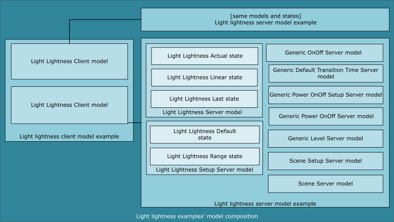
The example is composed of two minor examples that use the Light Lightness Client and Setup Server model:
- Light lightness server model example
- Light lightness client model example
For more information about the Light Lightness Client and Server model, see also the Bluetooth SIG's Bluetooth mesh model overview.
For provisioning purposes, the example requires either the provisioner example that is provided in the Provisioner example or the nRF Mesh mobile app.
Both the light lightness server and light lightness client examples have the provisionee role in the network. They support provisioning over Advertising bearer (PB-ADV) and GATT bearer (PB-GATT) and also support Bluetooth mesh Proxy Service (Server). Read more about the Proxy feature in GATT provisioning and Proxy.
Table of contents
- Light lightness client model example
- Light lightness server model example
- Light Lightness Client and Setup Server model
- Hardware requirements
- Software requirements
- Setup
- Testing the example
Light lightness client model example
The light lightness client model example has a provisionee role in the network. It implements two instances of the Light Lightness Client model. These instances are used to control the brightness of the LED 1 on the servers, the range of supported lightness levels, and the default lightness value after the servers' boot-up.
Light lightness server model example
The light lightness server model example has a provisionee role in the network. It implements one instance of the Light Lightness Setup Server model.
This model instance is used to receive the lightness level and change the brightness of the LED 1 on the server board, whenever the Light Lightness Actual or Light Lightness Linear state is changed. A change in the Light Lightness Actual state is reflected in the Light Lightness Linear state, and the other way around.
The model instance uses the APP_PWM library of the nRF5 SDK to control the brightness of the LED. To map the lightness level to the allowed range of the PWM ticks, the value of the Light Lightness Actual state is converted to the value of the Generic Level state.
Scene model
The light lightness server model example also implements one instance of the Scene Setup Server model. The Scene Setup Server instance can be used together with the Scene Client, although both model instances are optional and can be excluded. The Scene Server model uses the Default Transition Time Server instance instantiated in the Light Lightness Setup Server model instance.
For the values stored and recalled by the Scene model, see the Bluetooth Mesh Model Specification (MshMDLv1.0.1), Table 6.118. For more information on how to use the Scene models, see the scene example.
Light Lightness Client and Setup Server model
The Light Lightness Client model is used for manipulating the following states associated with the peer Light Lightness Setup Server model:
- Light Lightness Actual
- Light Lightness Linear
- Light Lightness Default
- Light Lightness Last
- Light Lightness Range
More information about the Light Lightness models can be found in the Light Lightness model documentation.
Hardware requirements
You need at least two compatible development kits for this example:
- One compatible development kit for the client.
- One or more compatible development kits for the servers.
Additionally, you need one of the following for provisioning:
- One compatible development kit for the provisioner if you decide to use the static provisioner example.
- An iOS or Android smartphone if you decide to provision using the nRF Mesh mobile app mobile application.
See Compatibility for information about the compatible development kits.
- Note
- This example uses the PWM peripheral to control the brightness of the LED. For this reason, it cannot be run on nRF51 devices, even after solving the issues related to their deprecated compatibility.
Software requirements
Depending on the provisioning method:
- If you decide to provision using a mobile application, you need nRF Mesh mobile app (iOS or Android) installed on the smartphone.
- If you decide to use the static provisioner example, you need the provisioner example.
Setup
You can find the source code of this example in the following folder: <InstallFolder>/examples/light_lightness
LED and button assignments
- Server:
- LED 1: Reflects the value of the Light Lightness Actual state on the server.
- When interacting with the boards:
- You cannot use buttons on the server boards, because the light lightness setup server example does not use the
simple_halmodule. - Instead of the buttons on the server boards, use the following RTT input:
RTT input DK Button Effect 1- The lightness value for LED 1 (and its brightness) is decreased in large step. 2- The lightness value for LED 1 (and its brightness) is increased in large step. 4- All Bluetooth mesh data is erased and the device is reset.
- You cannot use buttons on the server boards, because the light lightness setup server example does not use the
- Client:
- When interacting with the boards, you can use one of the following options:
- RTT input (recommended): Due to a limited number of buttons on the DK board, use the following RTT input when evaluating this example:
- Buttons: If you decide to use the buttons on the DK instead of the RTT input, you can only change the Light Lightness Actual state by sending Light Lightness Set Unacknowledged messages.RTT input DK Button Effect 1Button 1 The actual lightness value is increased in large steps and the Light Lightness Set Unacknowledged message is sent. 2Button 2 The actual lightness value is decreased in large steps and the Light Lightness Set Unacknowledged message is sent. 3Button 3 The actual lightness value in a linear scale is increased in large steps and Light Lightness Linear Set Unacknowledged message is sent. 4Button 4 The actual lightness value in a linear scale is decreased in large steps and Light Lightness Linear Set Unacknowledged message is sent. 5- The Light Lightness Last Get message is sent to request the last lightness value. 6- The Light Lightness Default Get message is sent to request the default lightness value. 7- The Light Lightness Range Get message is sent to request the range of supported lightness levels. 8- The Light Lightness Get message is sent to request the actual lightness value. 9- The Light Lightness Linear Get message is sent to request the actual lightness value in linear scale. a- The default light lightness value is increased and the Light Lightness Default Set Unacknowledged message is sent. b- The internal default light lightness value is decreased and the Light Lightness Default Set Unacknowledged message is sent. c- The internal minimum value of lightness levels range is increased and the Light Lightness Range Set Unacknowledged message is sent. d- The internal minimum value of lightness levels range is decreased and the Light Lightness Range Set Unacknowledged message is sent. e- The internal maximum value of lightness levels range is increased and the Light Lightness Range Set Unacknowledged message is sent. f- The internal maximum value of lightness levels range is decreased and the Light Lightness Range Set Unacknowledged message is sent. g- The internal actual lightness value in a linear scale is set to 0 and the Light Lightness Linear Set message is sent. h- Switches the client instance to be used for sending messages.
- RTT input (recommended): Due to a limited number of buttons on the DK board, use the following RTT input when evaluating this example:
- When interacting with the boards, you can use one of the following options:
Scene model integration
Scene Setup Server model instance is used by default by this example. You can exclude it by setting SCENE_SETUP_SERVER_INSTANCES_MAX to 0 (from the default value of 1) in examples/light_lightness/server/include/nrf_mesh_config_app.h.
If you decide to exclude the Scene Setup Server model instance, exclude it also from the Provisioner example if you want to evaluate using the static provisioner.
Testing the example
To test the light lightness example, build the examples by following the instructions in Building the Bluetooth mesh stack.
After building is complete, use one of the following methods, depending on the preferred provisioning approach:
Evaluating using the static provisioner
See provisioner example testing section for detailed steps required to provision and configure the boards using the static provisioner.
Evaluating using the nRF Mesh mobile app
See Evaluating examples using the nRF Mesh mobile application for detailed steps required to provision and configure the boards using the nRF Mesh mobile app.
The following naming convention is used in the app:
- Each server board is
nRF5x Mesh Lightness Setup Server. - The client board is
nRF5x Mesh Lightness Client.
The following model instances must be configured in the app for this example:
- For the
nRF5x Mesh Lightness Setup Serverserver boards:- Mandatory: Light Lightness Setup Server, Light Lightness Server
- Optional (with Scene model integration included): Scene Setup Server, Scene Server
- For the
nRF5x Mesh Lightness Clientclient board: Light Lightness Client.
- Note
- The light lightness client example allows to control the Light Lightness states. For this purpose, it is enough to configure only the Light Lightness Setup Server and Light Lightness Server model instances. If you want to see how the binding works between the Light Lightness states and the Generic states, configure the generic models instantiated in the light lightness server model example and use the appropriate clients to control the Generic states.
Once the provisioning is complete, you can start interacting with the boards.
- Note
- You can also configure the publish address of the second Light Lightness Client model instance. To do this, repeat step 3 from binding nodes and all steps from setting publication.
Interacting with the boards
Once the provisioning and the configuration of the client node and of at least one of the server nodes are complete, you can press buttons on the client or send command numbers using the RTT Viewer to observe the changes in the brightness of the LED 1 on the corresponding server boards.
The following set of message types is available for this demonstration:
- Light Lightness Set Unacknowledged
- Light Lightness Get
- Light Lightness Linear Set
- Light Lightness Linear Set Unacknowledged
- Light Lightness Linear Get
- Light Lightness Default Set Unacknowledged
- Light Lightness Default Get
- Light Lightness Range Set Unacknowledged
- Light Lightness Range Get
- Light Lightness Last Get
See LED and button assignments section for the full list of available commands.
If any of the devices is powered off and then back on, it will remember its flash configuration and rejoin the network. It will also restore values of the Light Lightness states. For more information about the flash manager, see Flash manager.
Controlling the lightness value
You can control the lightness value of the LED 1 using the RTT commands 1 - 4 or the buttons 1 - 4 on the board. Use the RTT commands 8 and 9 to retrieve the current lightness value in the perceived (Actual) lightness or the measured (Linear) lightness value accordingly.
To set the lightness value to 0, use the RTT command g.
For more information about the difference between the Actual and the Linear lightness values, see Bluetooth mesh model specification appendix A.2.
Changing behavior on power-up
You can change how the lightness value will be restored during a power-up sequence. This can be done by controlling the Generic OnPowerUp state instantiated by the Light Lightness Setup Server model.
The following table describes how the lightness value will be restored:
| On PowerUp value | Lightness value |
|---|---|
| 0 | 0 |
| 1 | The value of the Light Lightness Default state is used if it is not a zero. Otherwise, the Light Lightness Last state will be used. |
| 2 | Last known value for the Light Lightness Actual before power down. |
Use the RTT commands a and b to change the Light Lightness Default state, and the RTT commands 5 and 6 to retrieve the current last and default values. See LED and button assignments for additional commands.
The factory default values for these states are controlled through the following defines:
- LIGHT_LIGHTNESS_DEFAULT_ON_POWERUP
- LIGHT_LIGHTNESS_DEFAULT_LIGHTNESS_DEFAULT
- LIGHT_LIGHTNESS_DEFAULT_LIGHTNESS_LAST
- LIGHT_LIGHTNESS_DEFAULT_LIGHTNESS_ACTUAL
If you want to edit the factory default values, do this in nrf_mesh_config_app.h of the Light Lightness Setup Server example. Follow instructions in Testing the example to re-build and re-provision the example.
Restricting the range of the lightness value
You can restrict the range of the lightness value by changing the Light Lightness Range state. The new value of the Light Lightness Range state will be reflected in the Light Lightness Actual state at the next lightness value change.
Use RTT commands c, d, e, and f to change the Light Lightness Range state, and the RTT command 7 to retrieve the current range. See LED and button assignments for additional commands.
The factory default values for the minimum and maximum possible range values are controlled through LIGHT_LIGHTNESS_DEFAULT_RANGE_MIN and LIGHT_LIGHTNESS_DEFAULT_RANGE_MAX values in the nrf_mesh_config_app.h file of the light lightness server model example.
Other factory default configuration
In addition to the parameters described in the previous sections, you can also set the factory default transition time in milliseconds when changing the lightness levels. To do this, redefine the LIGHT_LIGHTNESS_DEFAULT_DTT value of the Generic Default Transition Time state in the nrf_mesh_config_app.h file of the light lightness server model example.