- Note
- This example is not supported by the nRF52810 Series.
This example demonstrates:
- how a PTM215B EnOcean switch can be integrated in the mesh ecosystem;
- how to capture the commissioning data of the EnOcean switch;
- how to translate the EnOcean switch messages into equivalent mesh messages.
The example uses two instances of the Generic OnOff client model. These on/off clients can be configured to control desired servers by the provisioner.
The following figure shows such a hybrid network that contains a device outside of the Bluetooth Mesh Network, a translator client, and servers. All servers have the relay functionality enabled, which allows the EnOcean switch to control the state of any of the servers in the network.
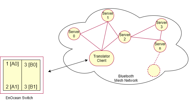
The translator client linked with the EnOcean switch has a provisionee role in the network. The client receives messages from the PTM215B switch and converts them to equivalent on/off client messages to control the state of LED 1 on servers. The client instantiates two instances of the Generic OnOff Client model (A and B, each with two buttons) and can either be provisioned and configured by the static provisioner (provisioner example that is part of the light switch example) or by a GATT-based provisioner (nRF Mesh mobile app).
Table of contents
Hardware requirements
You need at least two supported boards for this example:
- One development board for the EnOcean switch.
- One or more development boards for the servers.
Additionally, you need one of the following:
- one development board for the provisioner if you decide to use the static provisioner example.
- nRF Mesh mobile app (iOS or Android) if you decide to provision using the application.
See Compatibility for information about the supported boards.
Software requirements
To test this example, you need to use the server example from the light switch example folder, regardless of the number of server boards you use: <InstallFolder>/examples/light_switch/server
The example is configured to store security material for two EnOcean switches. If you want this example to support more than two EnOcean switches in parallel, set the value of MAX_ENOCEAN_DEVICES_SUPPORTED to the desired number of switches.
Additionally, if you decide to use the static provisioner example, you also need the light switch provisioner example firmware: <InstallFolder>/examples/light_switch/provisioner
See the Light switch example page for more information about the provisioner and the server examples. For details about the API usage of these two examples, check the provisioner details and server details pages.
Setup
You can find the source code of the EnOcean example in the following folder: <InstallFolder>/examples/enocean_switch
LED and button assignments
- Server
- During provisioning process:
- LED 3 and 4 blinking: Device identification active.
- LED 1 to 4: Blink four times to indicate provisioning process is completed.
- After provisioning and configuration is over:
- LED 1: Reflects the value of OnOff state on the server.
- LED ON: Value of the OnOff state is 1 (
true). - LED OFF: Value of the OnOff state is 0 (
false).
- LED ON: Value of the OnOff state is 1 (
- LED 1: Reflects the value of OnOff state on the server.
- During provisioning process:
- EnOcean client
- During provisioning process:
- LED 3 and 4 blinking: Device identification active.
- LED 1 to 4: Blink four times to indicate provisioning process is completed.
- Capturing commissioning telegrams:
- LED 1 to 4: Blink four times to indicate a commissioning telegram is captured.
- For node reset:
- Button 4 (on the board): Reset the node by erasing mesh and application data.
- LED 1: Blinks twice to indicate node reset is being executed.
- During provisioning process:
- Provisioner
- Button 1: Start provisioning.
- LED 1: Reflects the state of the provisioning.
- LED ON: Provisioning of the node is in progress.
- LED OFF: No ongoing provisioning process.
- LED 2: Reflects the state of the configuration.
- LED ON: Configuration of the node is in progress.
- LED OFF: No ongoing configuration process.
Testing the example
To test the EnOcean switch example, build the examples by following the instructions in Building the mesh stack.
- Note
- If you have more than 30 boards for the server and decided to use the static provisioner example, set
SERVER_NODE_COUNT(inlight_switch_example_common.h) to the number of boards available and rebuild the provisioner example.
After building is complete, use one of the following methods, depending on the preferred provisioning approach:
Once the provisioning is complete, you can start interacting with the boards.
Evaluating using the static provisioner
- Flash the examples by following the instructions in Running examples, including:
- Erase the flash of your development boards and program the SoftDevice on each board.
- Flash the light switch provisioner firmware on one board, this example on another board, and the light switch server firmware on other board or boards.
- Decide whether to start capturing the commissioning data at this point. You can also do this after the translator client provisioning.
- Connect RTT viewer to view the RTT output generated by the translator client and the provisioner.
- Press Button 1 on the provisioner to start the provisioning process. The provisioner prints details about the provisioning and the configuration process in the RTT log.
- Observe that when provisioner is scanning and provisioning a device, LED 1 on the provisioner board is turned ON.
- Observe that when configuration procedure is in progress, also LED 2 on the provisioner board is turned ON.
- Wait until LED 1 on the provisioner board remains ON steadily for a few seconds, which indicates that all available boards have been provisioned and configured.
If the provisioner encounters an error during the provisioning or configuration process for a certain node, you can reset the provisioner to restart this process for that node.
Evaluating using the nRF Mesh mobile app
- Flash the examples by following the instructions in Running examples, including:
- Erase the flash of your development boards and program the SoftDevice on each board.
- Flash this example on one board and the server firmware on other board or boards.
- Decide whether to start capturing the commissioning data at this point. You can also do this after the translator client provisioning.
- Open the nRF Mesh app.
- Provision the nodes. The switch board is
nRF5x Mesh Enocean Translator, the server board isnRF5x Mesh Light. - Bind the Generic OnOff client and server model instances on the nodes with the same app key:
- Select the Network tab.
- On the server board tile, tap the Configure button to open Node Configuration.
- Expand the Elements section and tap Generic Level Server.
- In the Bound App Keys section, tap the Bind Key button and select the app key.
- On the switch board tile, tap the Configure button to open Node Configuration.
- Expand the Elements section and tap Generic OnOff Client.
- In the Bound App Keys section, tap the Bind Key button and select the app key.
- In the client Node Configuration, expand the Elements section.
- Select the first Generic OnOff Client model instance.
- In the Publish section, set the Publish Address to one of the following addresses of the server nodes:
- unicast address of any server node;
- group addresses – if you choose this option, remember to subscribe the server nodes to these group addresses.
- Note
- You can also configure the Publish Address of the second Generic OnOff Client model instance to the unicast address of any other server node.
Any unhandled error is indicated by turning on all the LEDs on the board in steady state. You will need to reset the board to restart the application.
Capturing the commissioning data of the EnOcean switch
- Note
- These steps can be done either before or after the translator client has been provisioned.
To capture the commissioning data of the EnOcean switch, put the EnOcean switch in the radio-based commissioning mode:
- Make sure that the Disable Radio Commissioning flag in the Configuration register of the NFC interface is set to
0b0(default state). - Start by selecting one button contact of PTM 215B. Any button of PTM 215B (A0, A1, B0, B1) can be used.
- Execute the following sequence:
- Press and hold the selected button for more than 7 seconds before releasing it.
- Press the selected button quickly (hold for less than 2 seconds).
- Press and hold the selected button again for more than 7 seconds before releasing it. Upon detection of this sequence, PTM 215B enters the commissioning mode. See EnOcean PTM215B Datasheet for reference.
Once entered the radio commissioning mode, PTM215B transmits the commissioning telegrams. These telegrams will be captured by the translator, and the security material contained within those telegrams will be stored in the flash.
Once one of the commissioning telegrams is captured by the translator, 4 LEDs will blink 4 times.
- Note
- The example supports two EnOcean switches to be connected in parallel. You can repeat the commissioning configuration steps to commission the second switch. From the mesh network's perspective, both switches will be seen as one device, and their messages will be forwarded through the same Generic OnOff clients.
Interacting with the boards
Once the provisioning and the configuration of the EnOcean translator client node and at least one of the server nodes are complete and the commissioning data is captured, you can press rocker switches on the EnOcean switch to control various servers. See LED and button assignments section.
If any of the devices is powered off and back on, it will remember its flash configuration and rejoin the network. For more information about the flash manager, see Flash manager.
If you want to reset the application data without re-flashing the firmware, press Button 4. LED 1 will blink twice to indicate that application specific data and mesh related data has been erased. Press Reset button to reset the board and start the application.