Important: Before you run this example, make sure to program the SoftDevice.
This Zigbee dynamic multiprotocol example demonstrates how to control multiple BLE peripherals using a multiprotocol BLE Central/ZED device.
Description
The device is combining two application roles:
- BLE role – as a Central it connects to a specified number of Thingy:52 devices and enables the control for the application.
- Zigbee role – as a sleepy end device it represents a device with two color light bulb endpoints.
In the application, both roles are connected to create a relationship between two Zigbee endpoints and two Thingy:52 devices. After a power-on, the device initializes the BLE stack and the Zigbee stack, and starts scanning. Simultaneously, the application tries to connect to the Zigbee network and the Thingy:52 devices. For every connected Thingy, the application discovers characteristics, reads the current LED characteristic value and the battery level, and changes Thingy's LED from breathing blue color to constant red.
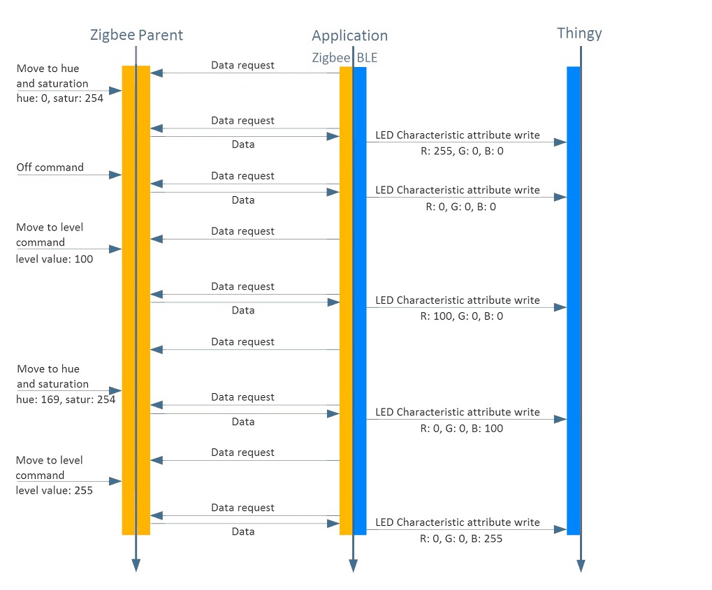
For every Zigbee endpoint in the relationship, incoming commands such as ON/OFF control, level control, or color control are processed. The commands control the LED on the Thingy that is related with the endpoint. See the following chart for an example of a working application.
LED assignments:
- BSP_LED_0 – Is ON when application is scanning on BLE.
- BSP_LED_1 – Is ON when Thingy connects, OFF when scanning.
- BSP_LED_2 – Is ON when the device is connected to the Zigbee network.
This application does not use buttons.
- Note
- Because of the discovery sequence, make sure that only Thingy:52 is connected to the application.
Setup
You can find the source code and the makefiles at <InstallFolder>\examples\multiprotocol\experimental\ble_zigbee_dynamic_color_light_bulb_thingy
Testing
- Precondition
- To test this example, prepare three nRF52840 Development Kits and one or two Thingy:52 IoT Sensor Kits.
The light switch example (see Zigbee Light Control example) allows for testing only one of the two endpoints. If you want to use a light switch to control the Thingy:52 LED, make sure that there are no other light bulb devices in the network. There is no guarantee that using more than one light switch will let you control both endpoints, because every light switch can connect to the same endpoint.
- Build the example according to the instructions in Building examples.
- In the light switch example, in
MATCH_DESC_REQ_ROLE, changeZB_NWK_BROADCAST_RX_ON_WHEN_IDLEtoZB_NWK_BROADCAST_ALL_DEVICESinmain.cto enable the light switch to work also with sleepy end devices:- Before the change: #define IEEE_CHANNEL_MASK (1l << ZIGBEE_CHANNEL) /**< Scan only one, predefined channel to find the Coordinator. */#define LIGHT_SWITCH_ENDPOINT 1 /**< Source endpoint used to control the light bulb. */#define MATCH_DESC_REQ_START_DELAY (2 * ZB_TIME_ONE_SECOND) /**< Delay between the light switch star-up and the light bulb finding procedure. */#define MATCH_DESC_REQ_TIMEOUT (5 * ZB_TIME_ONE_SECOND) /**< Time-out for the finding procedure. */#define MATCH_DESC_REQ_ROLE ZB_NWK_BROADCAST_RX_ON_WHEN_IDLE /**< Find only a non-sleepy device. */
- After the change: #define IEEE_CHANNEL_MASK (1l << ZIGBEE_CHANNEL) /**< Scan only one, predefined channel to find the Coordinator. */#define LIGHT_SWITCH_ENDPOINT 1 /**< Source endpoint used to control the light bulb. */#define MATCH_DESC_REQ_START_DELAY (2 * ZB_TIME_ONE_SECOND) /**< Delay between the light switch start-up and the light bulb finding procedure. */#define MATCH_DESC_REQ_TIMEOUT (5 * ZB_TIME_ONE_SECOND) /**< Time-out for the finding procedure. */#define MATCH_DESC_REQ_ROLE ZB_NWK_BROADCAST_ALL_DEVICES /**< Find a sleepy and a non-sleepy device. */
- Before the change:
- Build the light switch example from
<InstallFolder>\examples\zigbee\light_control\light_switch. - Build the Coordinator example from
<InstallFolder>\examples\zigbee\light_control\light_coordinator. - Flash the SoftDevice and the examples according to the instructions in Running examples.
- Start the Coordinator and wait until its BSP_LED_2 turns on.
- Start the application and the light switch.
When the Development Kit on which the application is running successfully joins the network, its BSP_LED_2 turns ON and the Thingy:52 LED changes color from breathing blue to constant red to indicate the established connection. As soon as both BSP_LED_2 and BSP_LED_3 on the light switch turn on, the light switch is ready to control one of the Thingy:52 LEDs. At this point, you can:
- Turn the LED on and off by pressing BSP_BUTTON_0 and BSP_BUTTON_1 on the light switch.
- Make the LED brighter or dimmer by pressing and holding BSP_BUTTON_0 and BSP_BUTTON_1 on the light switch.