The Internet Control Message Protocol (ICMP) is the control protocol of the IP stack that enables establishment of reachability, routes, and so on. This protocol is an integral part of any IP, but is unique as it is not a transport protocol to exchange data between hosts.
This application aims at demonstrating some of the ICMP functionality, like reaching link-local and global scopes as shown in Figure 1 and Figure 2 respectively.


Overview
This example demonstrates how Nordic's IPv6 stack can be used for sending and receiving ICMPv6 packets. Request and response formats used for this example are described in the section Requests and Responses.
Sending ICMP packets is triggered by the buttons on the kit. LEDs blinking indicates that response has been received.
ICMPv6 Data Exchange MSC
The MSC below provides an overview of the data exchange in the application between the node (nRF5x) and the router.
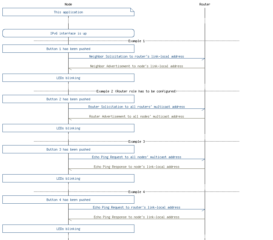
- Note
- No response is indicated by turning the LEDs off.
Common Modules Dependency and Usage
This section summarizes the usage of nRF5 resources and common modules in the examples, apart from the IoT 6LoWPAN and IPv6 stack library.
| Module | Inclusion/Usage | Description |
|---|---|---|
| Timer | 1 | One timer is used to make the LEDs blink on success. |
| Button | 4 | All four buttons of PCA10040 are used in this example. |
| LEDs | 4 | LEDs are used to indicate the application states. See LED assignments |
| Adv Data Encoder | Yes | Device name used is 'IPv6ICMP', IPSP Service UUID is included in the UUID list. |
| Scheduler | Yes | Scheduler is used for processing stack events. |
Setup
You can find the source code and the project file of the example in the following folder: <InstallFolder>\examples\iot\icmp
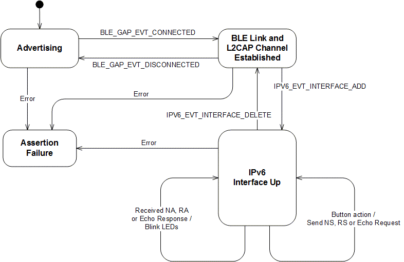
See the short state diagram below that describes the application states.
LED assignments
| Application State | LED 1 State | LED 2 State | LED 3 State | LED 4 State |
|---|---|---|---|---|
| Idle | OFF | OFF | OFF | OFF |
| Advertising | BLINKING | OFF | OFF | OFF |
| IPv6 Interface Up | OFF | ON | OFF | OFF |
| IPv6 Interface Down | ON | OFF | OFF | OFF |
| Operation success | OFF | ON | BLINK (approx. 1 s) | BLINK (approx. 1 s) |
| ASSERT | ON | ON | ON | ON |
- Note
- If commissioning is enabled, additional LED and Button assignments are made.
- If the application asserts, it is halted.
- This application is not power optimized!
Requests and Responses
The formats below present a simplified version of the ICMPv6 packets used in this example.
Neighbor Solicitation (NS) Packet Format
Press Button 1 to send the Neighbor Solicitation message of the following format:
| IPv6 Header | ICMP Header | ICMP Option | ICMP Option |
|---|---|---|---|
| Source and Destination address are link-local addresses (e.g. FE80::2AA:BBFF:FECC:DDEE) | Type: 135 (NS) | Source Link-Layer (SLLAO) | Address Registration (ARO) |
Neighbor Advertisement (NA) Packet Format
In response to a Neighbor Solicitation message, the router should respond with a Neighbor Advertisement packet with optional (if supported) ARO option.
| IPv6 Header | ICMP Header | ICMP Option |
|---|---|---|
| Source and Destination address are link-local addresses (e.g. FE80::2AA:BBFF:FECC:DDEE) | Type: 136 (NA) | Address Registration (ARO) |
Router Solicitation (RS) Packet Format
Press Button 2 to send a Router Solicitation message of the following format:
| IPv6 Header | ICMP Header | ICMP Option |
|---|---|---|
| Source address is link-local address (e.g. FE80::2AA:BBFF:FECC:DDEE) Destination is all router multicast address (FF02::2) | Type: 133 (RS) | Source Link-Layer (SLLAO) |
Router Advertisement (RA) Packet Format
In response to a Router Solicitation message, the router should respond with a Router Advertisement packet with optional prefix option (for creating IPv6 global address).
| IPv6 Header | ICMP Header | ICMP Option |
|---|---|---|
| Source and Destination address are link-local addresses (e.g. FE80::2AA:BBFF:FECC:DDEE) | Type: 134 (RA) | Prefix Option (PIO) |
- Note
- Peer node has to be configured to play the router role, in order to get this response.
Echo Request Packet Format
In order to send a Echo Request to all the nodes in the network, press Button 3 or 4 respectively. ICMP message has the following format:
| IPv6 Header | ICMP Header | Payload |
|---|---|---|
| Source and Destination address are link-local addresses (e.g. FE80::2AA:BBFF:FECC:DDEE) | Type: 128 (Echo Request) | 10x 'A' |
Echo Response Packet Format
In response to an Echo Request message, you should receive an Echo Response with the following format:
| IPv6 Header | ICMP Header | Payload |
|---|---|---|
| Source and Destination address are link-local addresses (e.g. FE80::2AA:BBFF:FECC:DDEE) | Type: 129 (Echo Response) | 10x 'A' |
Testing
See Connecting devices to the router for a list of relevant Linux commands.
- Compile and program the application. Observe that the advertising LED is lit.
- Prepare the Linux router device by initializing the 6LoWPAN module.
- Discover the advertising device by using the hcitool lescan command.
- Connect to the discovered device from the Linux console using the Bluetooth 6LoWPAN connect command.
- Observe that only the connected LED (LED 2) is lit.
- Press Button 1 on the kit.
- Observe that the LEDs are blinking for approx. 1 second - indicating that the Neighbor Advertisement was received.
- Prepare the Router role on the peer device (e.g. by turning on the RADVD daemon).
- Press Button 2 on the kit.
- Observe that the LEDs are blinking for approx. 1 second - indicating that the Router Advertisement was received.
- Press Button 3 on the kit.
- Observe that the LEDs are blinking for approx. 1 second - indicating that the Echo Response was received.
- Press Button 4 on the kit.
- Observe that the LEDs are blinking for approx. 1 second - indicating that the Echo Response was received.
- Disconnect from the device by using the Bluetooth 6LoWPAN disconnect command.
- Observe that only the advertising LED is lit.