Important: Before you run this example, make sure to program the SoftDevice.
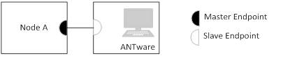
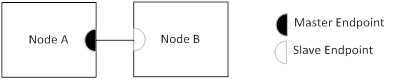
The ANT IO demo was designed to showcase basic bidirectional communication between two nodes using ANT, making use of the LEDs on one node to display the state of the buttons pressed on the other node. The demo can be used with either one development board and one ANT USB stick connected to the PC application ANTware or two development boards.
You can find the source code and project file of the example in the following folder: <InstallFolder>\examples\ant\experimental\ant_io_demo\ant_io_tx
You can find the source code and project file of the example in the following folder: <InstallFolder>\examples\ant\experimental\ant_io_demo\ant_io_rx
Testing
You can test the IO Demo example in different ways:
Testing the IO demo tx example using AntWare II
- Compile and program the IO demo tx example.
- Run AntWare II. Select your ANT PC dongle (for example, ANTUSB-m) from the available devices. Configure the device channel by loading the device profile configuration from the following file:
<InstallFolder>\examples\ant\experimental\ant_io_demo\ant_io_tx\ant_io_tx_test.xml. Alternatively, you can configure the device channel manually:- Set the channel assignment to slave.
- Set the channel ID to "0, 3, 1".
- Keep the default for all other settings.
- Click the Auto-Open button.
- Once the the slave endpoint has acquired the master (indicated by receiving broadcasts in the ANTWare Log window), you can begin to test the buttons and LEDs on the board.
- Click on the “Simulation” tab on the right-hand side of the ANTware application. Modify the “Respond With” field to either of these values:
Tx Buffer Value Description 01-00-00-00-00-00-00-FE Turns on BSP_LED_0 on the IO Board 01-00-00-00-00-00-00-FD Turns on BSP_LED_1 on the IO Board 01-00-00-00-00-00-00-FB Turns on BSP_LED_2 on the IO Board 01-00-00-00-00-00-00-F7 Turns on BSP_LED_3 on the IO Board - Check the “Auto Send Response to Received Msgs” check box. ANTware will now respond with a message of its own every time it receives an ANT broadcast message to control the LEDs on the IO board.
- The buttons on the IO board will allow you to modify the contents of the broadcast messages being transmitted to ANTware.
Testing the IO demo tx with IO demo rx
- Compile and program the IO demo tx example.
- Compile and program the IO demo rx example.
- Pressing the buttons on one of the nodes will control the state of the LEDs on the other node.