Table of Contents
Important: Before you run this example, make sure to program the SoftDevice.
This dynamic multiprotocol example application is based on the Door Lock, a Zigbee Home Automation device that steers the door lock. The device functionalities have been extended to support dynamic switching between two protocols, BLE and Zigbee, at the same time (concurrently). The door lock can be closed or opened through either the corresponding Zigbee ZCL commands or the BLE UART (with the device acting as a BLE peripheral).
To support both protocols at the same time, the Zigbee stack uses the 802.15.4 radio during the inactive time of the Bluetooth Low Energy radio (through Timeslot API). Depending on the Bluetooth low energy connection interval, the nRF52 SoC can spend up to 99% of the radio time on the Zigbee protocol. This is the same mechanism as the one used in the Thread's Dynamic multiprotocol examples.
For more information on multiprotocol operation, refer to the Multiprotocol support with BLE/Bluetooth support section.
- Note
- Transmitting and receiving data does not break connections from any of the radio protocols used (neither BLE nor Zigbee).
Moreover, the state of the door lock of the device in this example persists between power outages. The state of the lock is stored in the Flash Data Storage subsystem. You can also control the servo motor with the PWM (Pulse Width Modulation). The servo motor is fed from the pin LOCK_MECHANISM_PIN.
Setup
You can find the source code in the following folder: <InstallFolder>\examples\multiprotocol\ble_zigbee\ble_zigbee_dynamic_door_lock_nus
LED assignments
The example uses LED assignments as described in Thread BSP LED and button reference for the following LEDs:
- LED1 – Used inside multiprotocol examples to indicate the BLE connection state.
- LED3 – Used to indicate the Zigbee network connection state.
The following LEDs reserved for user application purposes are assigned in this example:
- LED4 – Used to indicate the state of the door lock:
- Off – Unlocked.
- On – Locked.
UART command assignments
The following BLE UART commands are configured in this example:
- "sesame" – Used to open the door.
- "hodor" – Used to close the door.
Testing
- Precondition
- To test this example, prepare two nRF52 Development Kits and a smartphone (Android or iOS). You also need an other board with CLI agent that will serve as a Zigbee Coordinator and also a Zigbee Door Lock Controller. See Zigbee CLI Agent example.
Before you start testing locking and unlocking the door, complete the following steps:
- On the smartphone, install nRF Toolbox for BLE.
- Prepare the Zigbee coordinator with the Zigbee CLI agent. Refer to Zigbee CLI Reference for complete reference of the Zigbee Command Line Interface.
- Compile and program the SoftDevice and the application. The BSP_INDICATE_ADVERTISING state is indicated.
- Connect to the device from nRF Connect (the device is advertising as 'Zigbee_Door_Lock'). The BSP_INDICATE_CONNECTED state is indicated.
- Disconnect the device in nRF Connect. The BSP_INDICATE_ADVERTISING state is indicated.
- Run the
rolecommand to set the state of the CLI device in the Zigbee network and then start it:> bdb role zcCoordinator setDone> bdb startStarted coordinatorDone - Observe that the LED3 indicates that the device has commissioned.
- Observe that the LED4 indicates that the door is open (state of the door lock is unlocked).
- Get the address of the Door Lock using Match Descriptor Request: > zdo match_desc ffff ffff 0104 1 0101 0src_addr=47D8 ep=8Done
- Note
- The short address of the device returned by the Match Descriptor Request might differ in your case.
- Get the IEEE address of the Door Lock: > zdo ieee_addr 0x47D80b010e1585785ce7Done
- Note
- The long address of the device returned by the Extended Address Request might differ in your case.
Locking the door
To lock the door, use the following ZCL command:
Observe the change of state on the LED or PWM, or both.
Unlocking the door
To unlock the door, use the following ZCL command:
Observe the change of state on the LED or PWM, or both.
Locking and unlocking the door with nRF Toolbox
- Open nRF Toolbox and choose the UART application.
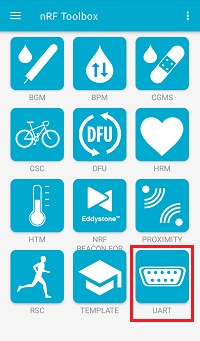 nRF Toolbox - UART application
 - Tap EDIT.
- Configure two application buttons:
- Enter command "sesame" for opening the door.
- Enter command "hodor" for closing the door.
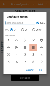 nRF Toolbox - UART application - Configure button
- After all buttons are configured, tap DONE.
- Tap CONNECT.
- Select the Zigbee_Door_Lock device.
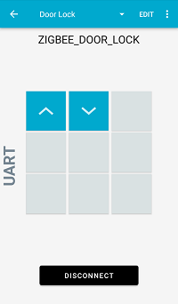 nRF Toolbox - UART application after establishing the connection
 - Observe that LED1 on the multiprotocol light switch board is turned on, which indicates that a BLE connection has been established.
You can now control the door lock by issuing Open command ("sesame") and Close command ("hodor") from your smartphone. Every time you issue a command, you can observe the change of the LED4 or PWM levels, or both.