Table of Contents
Important: Before you run this example, make sure to program the SoftDevice.
This Zigbee dynamic multiprotocol example demonstrates how to control multiple BLE peripherals using a multiprotocol BLE Central/ZED device. For more information on multiprotocol operation, refer to the Multiprotocol support with BLE/Bluetooth support section.
The device is combining the following two application roles:
- BLE role – as a Central, it connects to up to two Thingy:52 devices
- Zigbee role – as a sleepy end device, it represents a device with three endpoints, each with color light bulb functionality.
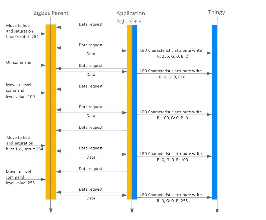
Two of the endpoints on the device are used to represent the connected Thingy:52 devices. These endpoints act as a 'proxy' between Zigbee and BLE. This means that Zigbee commands performed on the endpoint are mapped to BLE operations. For example, sending a ZCL On/Off cluster command to the proxy endpoint will result in writing the LED Control Characterstics on the Thingy. The remaining endpoint of the device can be used to control an optional RGB LED shield attached to the device.
After the power-on, the device initializes the BLE stack and the Zigbee stack. It then attempts to connect to the Zigbee network. If successful, the device starts scanning for Thingy:52 devices. If a device is found, the application attempts to connect to the device. For every connected Thingy, the application discovers characteristics, reads the current LED characteristic value and the battery level, and changes Thingy's LED from breathing blue color to constant red.
For every Zigbee endpoint in the relationship, incoming commands such as ON/OFF control, level control, or color control are processed. The commands control the LED on the Thingy that is related with the endpoint. See the following chart for an example of a working application.
Setup
You can find the source code and the makefiles at <InstallFolder>\examples\multiprotocol\experimental\ble_zigbee_dynamic_color_light_bulb_thingy
LED assignments
The example uses LED assignments as described in Thread BSP LED and button reference for the following LEDs:
- LED1 – Used inside multiprotocol examples to indicate the BLE connection state.
- LED3 – Used to indicate the Zigbee network connection state.
The following LEDs reserved for user application purposes are assigned in this example:
- LED2 – Used to indicate when at least one Thingy is connected.
Button assignments
The following buttons reserved for user application purposes are assigned in this example for the endpoints:
- Button 4 – Toggles the Finding & Binding mode on the local endpoint on or off.
- Thingy Button – Toggles the Finding & Binding mode on the endpoint representing Thingy:52 device on or off.
Testing
- Precondition
- To test this example, prepare three nRF52 Development Kits and one or two Thingy:52 IoT Sensor Kits.
To start testing, build the examples, flash the examples and the SoftDevice, and start the Development Kits:
- Build the example according to the instructions in Building examples.
- Build the BLE UART and Zigbee Color Dimmer Light Switch example from
<InstallFolder>\examples\multiprotocol\ble_zigbee\ble_zigbee_dynamic_light_switch_nus. - Build the Coordinator example from
<InstallFolder>\examples\zigbee\light_control\light_coordinator. - Flash the SoftDevice and the examples according to the instructions in Running examples.
- Start the Development Kit with the Coordinator and wait until it opens a new Zigbee network.
- Start the Development Kit with the application and wait until its LED3 turns on.
- Start the Development Kit with the Color Dimmer Light Switch and wait until it connects to the Zigbee network.
Once the Development Kit on which the application is running successfully connects to a Thingy:52, the LED on the Thingy:52 changes color from breathing blue to constant red.
Controlling endpoints
To control any of the endpoints (the local RGB endpoint or the proxy Thingy52 endpoint), you must pair with the Finding & Binding procedure:
- Do one of the following:
- Press Button 4 on the Development Kit to pair the local endpoint.
- Press Thingy Button to pair the given Thingy.
- Press the button that triggers Finding and Binding on the Color Dimmer Light Switch to pair the selected endpoint.
To pair more endpoints, cycle endpoint on the Color Dimmer Light Switch and repeat the Finding & Binding pairing procedure above.
Once the pairing with the Finding & Binding procedure is done, you can use the Light switch buttons to toggle the LED ON and OFF, change the brightness of the LED, or cycle endpoints. See the Button assignments section for details.