Table of Contents
Important: Before you run this example, make sure to program the SoftDevice.
This dynamic multiprotocol example application is based on the Color Dimmer Switch, a Zigbee Home Automation device. This device can turn on and off several compatible light bulbs, dim them, and change their color. With this example, the device supports dynamic switching between two protocols, BLE and Zigbee, at the same time (concurrently). Furthermore, this example makes use of Finding & Binding feature, which allows the device to discover its peers on the network.
This example uses at least three devices:
- Zigbee light switch (multiprotocol)
- Zigbee coordinator
- Zigbee light bulb (one or more)
The light switch device operates through pressing buttons on the DK on the Zigbee network, and through the Nordic UART Service on the BLE network. Both networks are independent from each other. Three different Zigbee Endpoints are instantiated on the light switch (with numbers 1, 2, and 3), with the possibility to trigger Finding & Binding process on each of them.
To support both protocols at the same time, the Zigbee stack uses the 802.15.4 radio during the inactive time of the Bluetooth Low Energy radio (using Timeslot API). Depending on the Bluetooth Low Energy connection interval, the nRF52 SoC can spend up to 99% of the radio time on the Zigbee protocol. This is the same mechanism as the one used in Dynamic multiprotocol examples in Thread.
For more information on multiprotocol operation, refer to the Multiprotocol support with BLE/Bluetooth support section.
- Note
- Transmitting and receiving data does not break connection from any of the used radio protocols, either BLE or Zigbee.
- Despite being based on the Color Dimmer Switch, the example does not necessarily need a Color Dimmable Bulb to operate. It can cooperate with any Zigbee device that uses On/Off cluster, Level Control cluster, Color Control cluster, or a combination of these clusters.
- The light switch of this example can be used with the CLI Agent example to establish control with a light bulb.
Setup
You can find the source code in the following folder: <InstallFolder>\examples\multiprotocol\ble_zigbee\ble_zigbee_dynamic_light_switch_nus
To show the basic behavior of the device, you need two other examples that contain a Zigbee coordinator and a Zigbee light bulb. With these two examples, you can control the light bulb (On/Off and Level Control clusters). You can find these examples in Zigbee Light Control example.
- Note
- You can use the Arudino Joystick shield v1.A with this example. Plug it in the nRF52 Development Kit, define the ARDUINO_JOYSTICK_SHIELD_V1A in code, and control the device using the built-in Joystick.
Assignments
You can control the devices either with the buttons on the development kits or the NUS UART commands in the nRF Toolbox application. The NUS UART commands offer more options than the DK buttons.
LED assignments
The example uses LED assignments as described in Thread BSP LED and button reference for the following LEDs:
- LED1 – Used inside multiprotocol examples to indicate the BLE connection state.
- LED3 – Used to indicate the Zigbee network connection state.
The following LEDs reserved for user application purposes are assigned in this example:
- LED2 – Used to indicate the Finding & Binding process state:
- On – In progress.
- Off – Not in progress.
- LED4
- Blinking – Used to indicate the Zigbee Endpoint that is currently selected (number of flashes equals the endpoint number).
Button assignments
The following buttons reserved for user application purposes are assigned in this example:
- Button 1
- Short press – After successful commissioning (LED3 state), turns the Zigbee light bulb on.
- Note
- If the user decreases the brightness level to the minimum, the effect of turning on the light bulb might not be noticeable.
- Long press – Increases the brightness of the light bulb.
- Short press – After successful commissioning (LED3 state), turns the Zigbee light bulb on.
- Button 2
- Short press – After successful commissioning (LED3 state), turns off the Zigbee light bulb.
- Long press – Decreases the brightness of the light bulb.
- Button 3
- Pressed when resetting the board – Enables the Sleepy End Device behaviour.
- Short press – Switches the Light Switch Endpoint to the next one. After switching the Endpoint, the device sends a ZCL Identify Trigger Effect request, which results in blinking of the bound bulbs (if any).
- Button 4
- Short press – Starts or stops the Finding & Binding procedure on the currently selected Endpoint. The endpoint is bound with the Zigbee light bulb that is turned on, and in identifying process.
BLE UART command assignments
The following BLE UART commands are configured in this example:
| Command | Effect |
|---|---|
n | Turns on the Zigbee light bulb. |
f | Turns off the Zigbee light bulb. |
t | Toggles the Zigbee light bulb on or off. |
i | Increases the brightness level of the Zigbee light bulb. |
d | Decreases the brightness level of the Zigbee light bulb. |
sn | Selects the next Endpoint. |
sp | Selects the previous Endpoint. |
& | Starts or stops the Finding & Binding procedure on the currently selected Endpoint. |
h[vH]s[vS] | Moves the Color Bulb to the desired value of Hue and Saturation, [vH] and [vS] respectively, indicated by decimal values (from 0 to 255).Example: h25s150. |
[v] | [v] corresponds to a numeric value between 0 and 999. The command toggles the Zigbee light bulb after [v] seconds.Example: 33. |
Testing
For this example, prepare:
- at least three nRF52 Development Kits;
- a smartphone (Android or iOS).
Configuring the boards
To evaluate the example, first configure the boards:
- Run the following commands to flash the Zigbee Coordinator example to one of the boards (edit the SoC and PCA numbers if you use nRF52833): $ cd <InstallFolder>/examples/zigbee/light_control/light_coordinator/hex$ nrfjprog -f nrf52 -r --program nrf52840_xxaa_pca10056.hex --chiperase
- Run the following commands to flash the Zigbee dimmable light bulb example to all remaining boards (edit the SoC and PCA numbers if you use nRF52833): $ cd <InstallFolder>/examples/zigbee/light_control/light_bulb/hex$ nrfjprog -f nrf52 -r --program nrf52840_xxaa_pca10056.hex --chiperase
- Build this light switch example according to the instructions in Building examples.
- Flash SoftDevice and this light switch example according to the instructions in Running examples.
- Turn on all boards as described in Zigbee Light Control example (Testing section, steps 3 to 5).
- Press the Finding and Binding button on the light bulb board to start the identifying process on it.
- Press the Button 4 on the light switch board to bind the bulb from the previous step to the selected endpoint.
- If you have more bulbs available, press Button 3 on the light switch board to switch to the next endpoint. LED4 on the light switch board changes the flashing pattern.
- Repeat steps 8-9 to bind the new bulb to the new endpoint.
- Note
- If you have a custom 3rd-party Color Dimmable Light Bulb, commission it to the network and put it into the Identify mode - you could change its color as well.
Interacting with the boards
You can toggle the LED on the light bulb board bound to the currently selected endpoint in the network by pressing Button 1 and Button 2 on the light switch board.
After configuration, you can also start interacting with the boards using the nRF Toolbox application:
- On the smartphone, install nRF Toolbox for BLE.
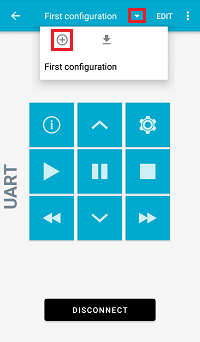
- Open nRF Toolbox and select the UART application.
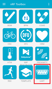 nRF Toolbox - UART application
 - Tap EDIT.
- Configure the following nine application buttons (also listed in the BLE UART command assignments table):
- Configure command
n - Configure command
f - Configure command
t - Configure command
i - Configure command
d - Configure command
sn - Configure command
sp - Configure command
& - Configure command
h12s34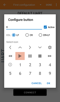 nRF Toolbox - UART application - Configure button
- Configure command
- When all buttons are configured, tap DONE.
- Tap CONNECT and select the Zigbee_Switch light switch device.
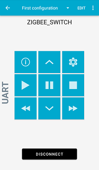 nRF Toolbox - UART application after establishing the connection
 - Observe that LED1 on the multiprotocol light switch board is turned on and stops blinking, which indicates that a BLE connection has been established.
- Test the application buttons by pressing the buttons you assigned in the application in step 4:
nandfcommands: Press the corresponding buttons to turn the LED on the Zigbee light bulb node on and off, respectively.tcommand: Press the corresponding button two times to toggle the LED on the Zigbee light bulb node on and off.ssnandspcommands: Move through the endpoints with the corresponding buttons.&command: Press the corresponding button to initiate the Finding & Binding procedure.- Hue and saturation command: Press the button configured to
h12s34to move to the predefined Hue and Saturation value. ianddcommands: Press the corresponding buttons to adjust the brightness level.
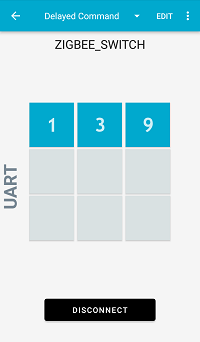
Testing the [v] command
To test the delayed toggle command ([v] command in the BLE UART command assignments table), add another button with the numeric command or create a separate configuration (screen).
For example, you can add buttons to toggle the light bulb after 1 (1 command), 3 (3 command), and 9 (9 command) seconds.