The UART HCI protocol implements the Serialization PHY API using the UART interface.
UART HCI for serialization uses four standard UART lines: RX, TX, /CTS, and /RTS. Hardware flow control is enabled. The protocol supports full duplex communication. The serialization version of the HCI protocol has a similar feature set as the stand-alone version provided in HCI transport library. However, implementation details are different due to API, signaling, and memory management required by the Serialization PHY API.

The packet format complies with the standard. However, because of memory shortage in the connectivity chip, the current implementation limits the packet size to 384 bytes. Every payload packet consists of a four-byte header followed by payload and CRC field.
The packet header contains SEQ, ACK numbers, data integrity check (DIP), reliable packet (RP) flags, LEN - numbers of bytes in the payload, and HCS - header checksum. Payload packets use TYPE=0xE - a vendor-specific type. Acknowledgment packets use TYPE=0x0, SEQ=0, DIP=0, RP=0, LEN=0.
The basic communication flow implemented in the HCI layer is shown in the figure below:

- Each payload packet requires an acknowledgment to complete a transmission. An acknowledgment packet has an ACK field set to a number that indicates the next expected SEQ number.
- When the acknowledgment packet is not received within a time-out window, the packet is retransmitted.
- When a packet with an invalid SEQ is received (for example, for a retransmitted packet due to lost acknowledgment packet), the receiver sends an ACK to indicate the next expected packet.
The driver is split into two layers - HCI and SLIP.
HCI LAYER
The HCI layer is implemented as two event-driven state machines with separated micro schedulers for events coming from SER_PHY, SLIP layers, and timer.
The operation of receiver and transmitter state machines is shown in the following UML state diagram:


SLIP LAYER
UART HCI SLIP packets are transmitted in the following format, where both TX_PACKET_START and TX_PACKET_END are a 0xC0 byte:
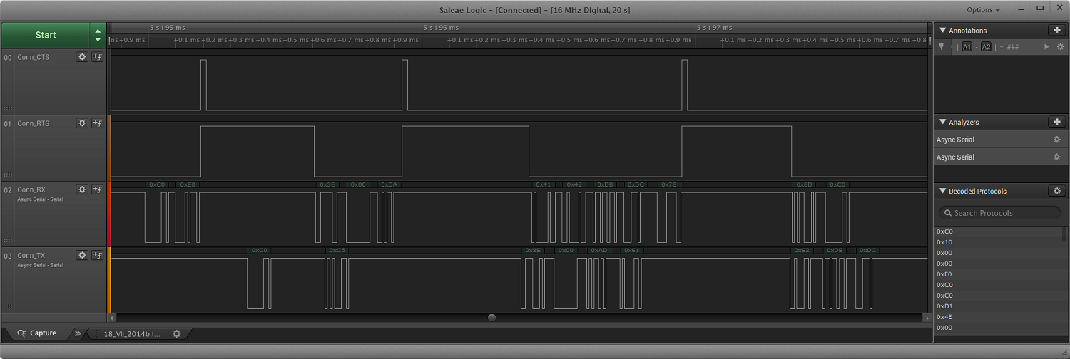
- On the RX line, you can observe a reception of a complete SLIP packet:
[RX_PACKET]=[0xC0 0xE8 0x3E 0x00 0xDA 0x41 0x42 0xDB 0xDC 0x78 0x8D 0xC0]At the beginning and the end of the packet, there are0xC0bytes that indicate packet start and packet end. - Between both
0xC0symbols, the content of the packet is received. It includes higher level (HCI) header, CRC, and payload. There is also a SLIP escape sequence present:[0xDB 0xDC], which is an encoded 0xC0 character. - On the TX line, a part of a SLIP packet is shown.
UART HCI SLIP driver
The UART HCI SLIP protocol for serialization is implemented in the ser_phy_hci_slip.c file. It uses the UART driver as a low-level driver.
The implementation is event-driven. Events from the low-level driver are handled in a static uart_event_handler() function. Three types of nrf_drv_uart_event_t events are processed: NRF_DRV_UART_EVT_ERROR, NRF_DRV_UART_EVT_TX_DONE, and NRF_DRV_UART_EVT_RX_DONE.
- In case of an NRF_DRV_UART_EVT_ERROR event, the error source (taken from the nrf_drv_uart_error_evt_t structure) is checked. If the source is parity or overrun error, then the upper layer is notified with the SER_PHY_HCI_SLIP_EVT_HW_ERROR event. Error source is passed in error_code member of the ser_phy_evt_hw_error_params_t structure.
- NRF_DRV_UART_EVT_TX_DONE indicates that another part of a packet has been successfully transmitted. Transmission of the subsequent part is then requested, or the upper layer is notified with the SER_PHY_HCI_SLIP_EVT_PKT_SENT event when the process is complete.
- Note
- When transmission of a packet begins, the nrf_drv_uart_tx() function is called for the first time from the ser_phy_tx_pkt_send() function. Later, it is only called from the nrf_drv_uart_event_t event callback.
- NRF_DRV_UART_EVT_RX_DONE indicates that another part of a packet has been successfully received. After the packet header is received, a request to the upper layer is made to provide a proper buffer for that packet. After the final part of the packet is received, the upper layer is notified that the packet has been received or dropped, based on the fact if the buffer was provided or not.
Following ser_phy_hci_slip_evt_type_t, the events are sent to the upper layer:
- SER_PHY_HCI_SLIP_EVT_PKT_SENT, when all bytes of the packet are transmitted.
- SER_PHY_HCI_SLIP_EVT_ACK_SENT, when all bytes of the ACK packet are transmitted.
- SER_PHY_HCI_SLIP_EVT_PKT_RECEIVED, when all bytes have been received. This event indicates how many bytes have been received to which memory address.
- SER_PHY_HCI_SLIP_EVT_HW_ERROR, when a hardware error is reported by the low-level driver.
Function ser_phy_open() initializes UART using the nrf_drv_uart_init() function and prepares for the reception of incoming packets. It also registers the ser_phy_hci_slip_evt_type_t event callback.
Function ser_phy_close() closes UART using the nrf_drv_uart_uninit() function. It also deregisters the ser_phy_hci_slip_evt_type_t event callback.