The QDEC Example demonstrates the use of the quadrature decoder (QDEC) peripheral.
The example uses the software quadrature encoder simulator QENC to produce input. The quadrature encoder simulator uses one channel of the GPIOTE module. The state of the encoder changes according to the sampling clock generated by the LED output.
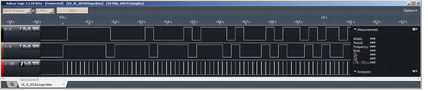
The QDEC inputs A and B must be connected to the QENC outputs A and B, respectively. The QDEC LED output must be connected to the QENC LED input.
QENC produces a variable number of positive and negative pulses in an infinite loop. These pulses are synchronized with the bursts of clock impulses that are generated by QDEC at the LED output. The pulses are counted by QDEC operating in a REPORT mode, and the count is compared with the pulses that are generated by QENC.
Setup
You can find the source code and the project file of the example in the following folder: <InstallFolder>\examples\peripheral\qdec
Configuration:
- QENC LED (pin 29) should be connected to QDEC LED (pin 28).
- QENC A (pin 31) should be connected to QDEC A (pin 3).
- QENC B (pin 30) should be connected to QDEC B (pin 4).
Testing
The example works in auto-test mode:
- Every time a pulse is received, an asterisk is printed on UART.
- If there is a difference between the number of pulses counted and generated, an error message is printed on UART and the application restarts.
- If no pulses are received, the pins are not connected properly. In this case, the example runs in an endless loop without printing any output after the welcome message.
Test the QDEC example application by performing the following steps:
- Connect the pins as described above.
- Compile and program the application.
- Start a terminal emulator like PuTTY and connect to the used COM port with the following UART settings:
- Baud rate: 115.200
- 8 data bits
- 1 stop bit
- No parity
- HW flow control: None
- Observe that a welcome message is output on the console.
- Observe that a series of asterisks is output on the console. If no asterisks are printed, check the pin connections.
- Observe for a while to make sure that no error messages are generated.