The Device Firmware Upgrade over TFTP is an example that uses the TFTP module and the Background DFU library to show how to update firmware using IPv6 connectivity.
To demonstrate support for background DFU on nRF52, Nordic's IPv6 stack and TFTP protocol are used.
This example implements a simple application which involves the Background DFU module providing the upgrading service as a background process.
- Note
- For demo purposes, see Creating DFU images for information about creating your own images.
- A demo requires an IPv6 TFTP server to download and upload files. For installing a simple TFTP server on Linux, see this section.
This example requires you to create new firmware images. For more information, see Creating DFU images.
The demo setup and flow diagram are presented in Figure 1.
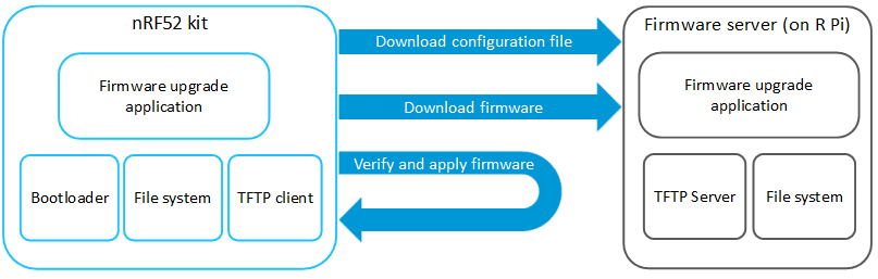
Overview
This example demonstrates how Nordic's IPv6 stack can be used for transmitting and receiving new firmware. It uses the TFTP module as a transport layer to transfer new firmware.
The application spends most of the time in normal IDLE mode. In the background, the software configuration file is downloading and checking every time the user pushes a button. The configuration file is located on the TFTP server and is read to determine when it should download and apply new firmware. It checks the current CRC32 firmware block and compares it with the values obtained from the configuration file. If DFU module decides to download new firmware, it starts downloading an init file used to perform a secure update. When the init file is downloaded, the Background DFU module starts retrieving the firmware image.
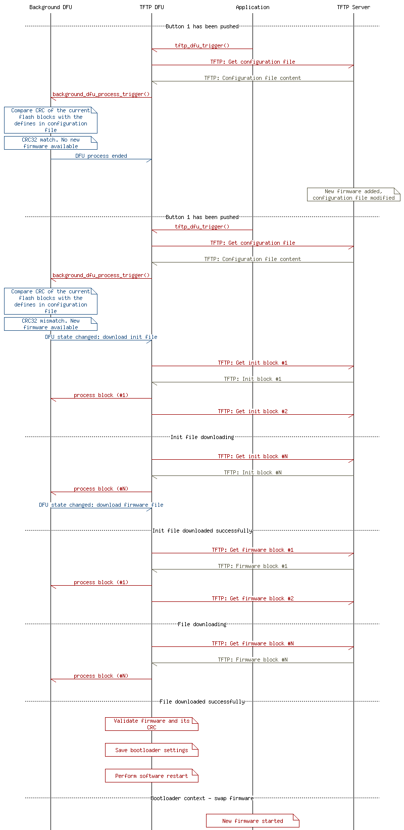
Data Exchange MSC
The MSC below provides an overview of the data exchange in the application between the node (nRF52) and the router/cloud in two instances:
- The device already has the correct application.
- There was an upgrade caused by a file configuration modification.
JSON configuration files
Each device has its own configuration file. The path for those files is created in the following way:
In the above file path:
- DEV_TYPE is a 16-bit device type number located inside the UICR register. This is usually located at the address 0x10001080 (by default: 65535).
- DEV_ID is a 16-bit device identification number located inside the UICR register. This is usually located at the address 0x10001084 (by default: 65535).
This file should be a JSON-formatted object that consists of a few parts: one per each firmware type, one for paths to init files, and one for paths to firmware images. For example:
Each part is described by four values and the path to the appropriate init file and firmware block:
- Size of the binary file in bytes.
- ID of the file, which in this example is a CRC32 control sum of a given block image.
- Size of the init file in bytes.
- ID of the init file, which in this example is a CRC32 control sum of a given init file.
- Path to the init file.
- Path to the binary file.
In order to configure new firmware, modify the JSON elements to match the new firmware path, size, and its CRC32, and place it in the corresponding field. If any type of image is not available for download, set the sizes and CRC to 0 and paths to empty string "". Use the trigger_creator.py Python script that is available in the example directory to prepare the JSON file automatically.
- Note
- In the current version, update of an application is the only supported scenario. The SoftDevice or bootloader cannot be updated using the Background DFU library.
Common module dependency and usage
This section summarizes the usage of nRF52 resources and common modules in the examples apart from the IoT 6LoWPAN and IPv6 stack library.
| Module | Inclusion/Usage | Description |
|---|---|---|
| Timer | 3 | Two timers - IoT timer, button module. |
| Buttons | 1 | One button is used to start downloading a firmware configuration file. |
| LEDs | 4 | LEDs are used to indicate that the application is still working and to show if it is connected. See LED assignments. |
| Scheduler | Yes | Scheduler is used for processing stack events. |
- Note
- To see how to read data from the UART interface see Using the UART interface.
Setup
You can find the source code and the project file of the example in the following folder: <InstallFolder>\examples\iot\tftp\background_dfu
LED assignments
| Application State | LED 1 State | LED 2 State | LED 3 State | LED 4 State |
|---|---|---|---|---|
| Advertising | BLINKING | OFF | OFF | OFF |
| IPv6 Interface Up | OFF | ON | OFF | OFF |
| IPv6 Interface Down | ON | BLINKING | OFF | OFF |
| ASSERT | ON | ON | ON | ON |
- Note
- If the application asserts, it is halted.
- This application is not power optimized!
Testing
See Connecting devices to the router for a list of relevant Linux commands.
Unless stated otherwise, run all of the presented commands in the main folder of the background DFU example: <InstallFolder>\examples\iot\tftp\background_dfu
- Create cryptographic keys for the example. For information about key generation, see Working with keys.
- Create a private key: nrfutil keys generate priv.pem
- Create a public key in code format and store it in a file named
dfu_public_key.c:nrfutil keys display --key pk --format code priv.pem --out_file dfu_public_key.c - Copy the
dfu_public_key.cfile to the project folder<InstallFolder>\examples\dfu, replacing the existing file.- Note
- Do not copy the key to folder
<InstallFolder>\examples\iot\tftp\background_dfu. Use the path provided above.
- Create a private key:
- Build the bootloader:
- Enter the
<InstallFolder>\examples\iot\bootloaderdirectory. - Compile the bootloader.
- Enter the
- Prepare the TFTP background DFU client:
- Install micro-ecc. This library is required by the Cryptography library - nrf_crypto, which is used by the background DFU example.
- Compile the DFU client by running the
makecommand in<InstallFolder>\examples\iot\tftp\background_dfu\pca10040\s132\armgcc. - Return to the main folder of the background DFU client example and generate a bootloader settings HEX file: nrfutil settings generate --family NRF52 --application pca10040\s132\armgcc\_build\nrf52832_xxaa.hex --application-version 1 --bootloader-version 1 --bl-settings-version 1 settings.hex
- Use mergehex (part of the nRF5x Command Line Tools) to merge the client HEX file and the bootloader settings HEX file: mergehex -m pca10040\s132\armgcc\_build\nrf52832_xxaa.hex settings.hex -o dfu_client.hex
- Flash the background DFU client to the board:
- Connect the TFTP DFU client board to the computer.
- Flash the SoftDevice as described in Programming SoftDevices.
- Flash the bootloader as described in Programming the bootloader.
- Flash the merged DFU client with the following command: nrfjprog -f nrf52 -r --program dfu_client.hex --sectorerase
- Make sure that the device is advertising. This is indicated by blinking LED 1.
- Prepare the firmware package for the DFU process:
- To successfully perform the DFU process, you need to modify the DFU client application, so that the new firmware has a different checksum. For example, add the following line to the
main()function:LEDS_ON(BSP_LED_3_MASK); - Compile the modified DFU client by running the
makecommand in<InstallFolder>\examples\iot\tftp\background_dfu\pca10040\s132\armgcc. - Return to the DFU example main folder and prepare a firmware package (in ZIP format) with the new firmware. For more information, see Creating a firmware package with nrfutil. Note that the application file name (including the path on the TFTP server) cannot exceed 32 characters. Rename the generated HEX file if needed, or the file will not be found.nrfutil pkg generate --hw-version 52 --sd-req 0xA5 --application-version 2 --application pca10040\s132\armgcc\_build\nrf52832_xxaa.hex --key-file priv.pem app_dfu_package.zip
- To successfully perform the DFU process, you need to modify the DFU client application, so that the new firmware has a different checksum. For example, add the following line to the
- Prepare a JSON config file and move the decompressed firmware and init files to appropriate directories accessible by TFTP server. Make sure the files permissions and owners are correct in the TFTP server folder (see this section for more information). python trigger_creator.py --tftp_path /dfu/app/ app_dfu_package.zip <TftpFolder>\dfu\c\65535\65535unzip app_dfu_package.zip -d <TftpFolder>\dfu\app\
- Press Button 1 to trigger the DFU procedure.
- Observe UART output to see if the new firmware has started downloading.
- Observe the LEDs. After a few minutes, the device should reboot, and all LEDs will turn off.
- If the upgrade process is successful, the device enters bootloader mode.
- After a few seconds, it should reset and start with the new application. Observe that the device is advertising.
- Check if the new application is correct. For example, see if LED 4 is turned on.
Using the UART interface
By default, the UART interface is connected to a computer via a J-Link virtual USB serial interface. In order to read from this interface:
- Connect a USB cable from your computer to the nRF52 board.
- Check the list of available serial (COM) ports. The new interface should appear there after connecting the board.
- Use any program that can read from the serial interface and point it to the read port.
Default UART configuration
| Property | Value |
|---|---|
| Baud rate | 115200 |
| Flow control | None |
| Data bits | 8 bits |
| Number of stop bits | 1 bit |
| Parity | None |