The serial transport makes it possible to perform secure Device Firmware Updates (DFU) over a serial link using UART. The transport layer uses the SLIP library for encoding and decoding packets.
Packet format
Each packet consists of a command and the parameters that are required for the command:
opcode data
The opcode is one byte of type serial_dfu_op_code_t. The following table lists the available opcodes and their parameters:
| Opcode | Procedure | Description | Parameters | Response value |
|---|---|---|---|---|
| 0x01 | Create | Creates an object with the given type and selects it. Removes an old object of the same type (if such an object exists). | Type (uint8_t), Size (uint32) Types:
Size:
| |
| 0x02 | Set Packet Receipt Notification (PRN) value | Sets the number of packets to be sent before receiving a Packet Receipt Notification. The default is 0. | Value (uint16, little endian) | |
| 0x03 | Calculate checksum | Requests the checksum of the object that was sent (applicable only for data objects). The checksum is reset after sending an Execute command. | None | Offset (uint32), CRC32 (uint32) |
| 0x04 | Execute | Executes the last object that was sent. | None | |
| 0x06 | Select | Selects the last object with the given type that was sent. | Type (uint8_t) Types:
| Maximum size (uint32), offset (uint32), CRC32 (uint32) |
| 0x07 | Get serial MTU | Retrieves the maximum transmission unit for the device. | MTU (uint16) | |
| 0x08 | Write object | Write data to the selected object. | data (uint8_t[]). | |
| 0x60 | Response Code | Request opcode, result code |
The following table lists the result codes that are sent as part of the response:
| Result code | Definition | Description |
|---|---|---|
| 0x00 | Invalid code | The provided opcode was missing or malformed. |
| 0x01 | Success | The operation completed successfully. |
| 0x02 | Opcode not supported | The provided opcode was invalid. |
| 0x03 | Invalid parameter | A parameter for the opcode was missing. |
| 0x04 | Insufficient resources | There was not enough memory for the data object. |
| 0x05 | Invalid object | The data object did not match the firmware and hardware requirements, the signature was missing, or parsing the command failed. |
| 0x07 | Unsupported type | The provided object type was not valid for a Create or Read operation. |
| 0x08 | Operation not permitted | The state of the DFU process did not allow this operation. |
| 0x0A | Operation failed | The operation failed. |
Message sequence charts
The following message sequence charts show the initialization and the transfer of an init packet and a firmware image, respectively.
Note that the message sequence charts do not show how the sent data is encapsulated into SLIP packets. See the documentation of the SLIP library for more information about how the encoding works.
Initialization
Before the actual DFU process can start, the DFU controller must set the Packet Receipt Notification (PRN) value and obtain the maximum transmission unit (MTU). In most cases, the PRN can be set to 0 to disable checksums being sent back to the controller during transfers. However, if the transport layer is unreliable, set the PRN to a value other than 0.
The MTU of the DFU target sets a limit on the packet size that can be sent. The MTU includes the SLIP encapsulation, which means that the maximum data size that can be sent is (MTU/2) - 2. (See SLIP library: The MTU must be divided by 2 to address the case where all bytes are escape characters. The 2 bytes that are subtracted are SERIAL_DFU_OP_CODE_WRITE_OBJECT and the start byte of SLIP.)
The following message sequence chart shows how the PRN is set and the MTU is obtained:

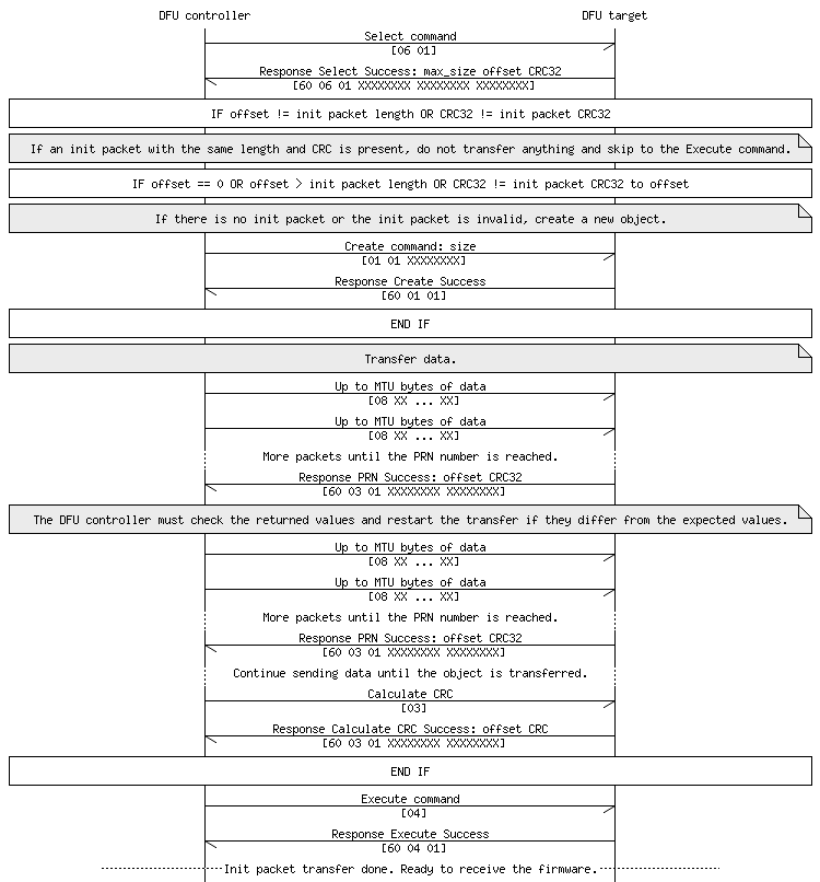
Transfer of an init packet
The DFU controller first checks if the init packet has already been transferred successfully. If not, the DFU controller checks if it has been transferred partially. If some data has been transferred already, the transfer is continued. Otherwise, the DFU controller sends a Create command to create a new data object and then transfers the init packet. When the init packet is available, the DFU controller issues an Execute command to initiate the validation of the init packet.
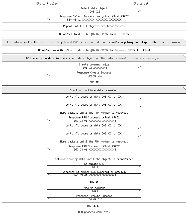
Transfer of a firmware image
A firmware image is split up into several data objects that are transferred consecutively. If the transfer of a data object fails (for example, because of a power loss), the transfer can be continued instead of restarted. Therefore, the DFU controller starts by selecting the last data object that was sent and checks if it is complete and valid. If it is, the controller issues an Execute command and then continues the transfer with the next data object. Otherwise, the DFU controller sends a Create command to create a new data object if required (thus if the transfer for this data object has not started yet or the received data is corrupted) and then transfers the next data object.
When all packets are transferred, the DFU controller issues an Execute command to trigger the actual firmware update.
The DFU controller is responsible for keeping track of the progress. The response to each Select command contains information about the maximum object size, the current offset, and the CRC. For example, if the image size is 10 kB and the maximum object size is 4 kB, 3 data objects must be transferred. If the returned offset is 6 kB, the DFU controller knows that the current object is the second object to transfer and that is has not been transferred completely.