The nRF5 SDK for Mesh provides APIs for interfacing external Front End Modules (FEMs) to increase the range of Bluetooth Low Energy communication.
Typically, these FEMs are controlled by the enable signals that turn on a power amplifier (PA) or a low noise amplifier (LNA) (see Interfacing PA/LNA with nRF52). These signals must be activated some time before the actual radio transmission or reception begins, to provide sufficient ramp-up time.
The Mesh PA/LNA module enables users to control such external components using GPIOs that are synchronized to the radio operation. The PA/LNA module drives the chosen GPIO pins according to the chosen polarity (Active High/Active Low).
To show how to use the Mesh PA/LNA module, we start with the light_switch/server example and add PA/LNA support to it.
Adding PA/LNA support to the application
First, select unused GPIO pins that can be used by the PA/LNA module. For this example, we use GPIO 25 for controlling the LNA and GPIO 24 for controlling the PA. Let's assume that the control signals required by the external hardware module are active high.
The Mesh PA/LNA module uses the nRF52832 PPI and nRF52832 GPIOTE hardware modules to generate these signals.
For this example, we choose the unused PPI channels 0 and 1, and GPIOTE channel 0.
Now, make the following changes in light_switch/server/src/main.c:
- Include the required module header file:
mesh_pa_lna.h - Create a static global variable of type mesh_pa_lna_gpiote_params_t and initialize it with the selected values:
static mesh_pa_lna_gpiote_params_t m_pa_lna_params = { .lna_cfg = { .enable = 1, .active_high = 1, .gpio_pin = 25 }, .pa_cfg = { .enable = 1, .active_high = 1, .gpio_pin = 24 }, .ppi_ch_id_set = 0, .ppi_ch_id_clr = 1, .gpiote_ch_id = 0 }; - Enable the PA/LNA module by calling mesh_pa_lna_gpiote_enable() after the call to
mesh_init():mesh_pa_lna_gpiote_enable(&m_pa_lna_params);
- To build the example, follow the instructions in Building the Mesh Stack. See How to run examples in the examples documentation for the commands required to program a device using
nrfjprog.
If you connect a logic analyzer to the GPIO pins 25 and 24, you should see them toggling.
Observe that the unprovisioned device sends the unprovisioned node beacons every two seconds (NRF_MESH_PROV_BEARER_ADV_UNPROV_BEACON_INTERVAL_MS) and scans for the incoming provisioning invite for the rest of the time.
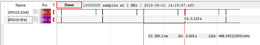
You will see brief active high pulses on GPIO 24, which we have used for the PA control. Similarly, GPIO 25, which we have used for the LNA control, is almost always ON except for the time when the radio switches to the next advertising channel (for scanning or for sending advertisements).
See the PA/LNA API documentation for more details.