This Quick Start Guide provides information on how to set up Nordic's Border Router solution.
The Border Router is intended for development purposes, to make it easy for developers to connect their Thread network to the Internet in the development phase. It also supports the Thread native commissioning procedure utilizing NFC to initiate the process.
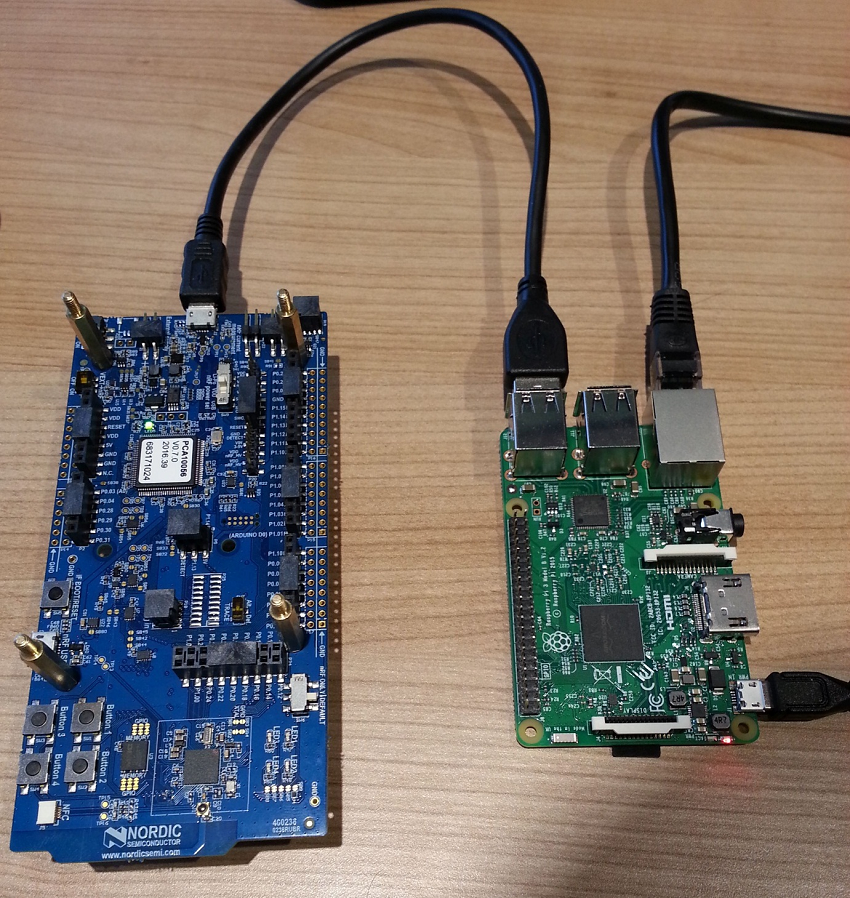
The Border Router consists of Raspberry Pi 3 B, NXP Semiconductors' NFC reader shield, and Nordic’s nRF52840 Development Kit. NXP Semiconductors' NFC reader shield is an optional element required for Thread native commissioning. However, the shield is not necessary to connect a Thread network to the Internet.
nRF52840 Development Kit acts as a connectivity chip running the Network Co-Processor (NCP) application. It communicates with Raspberry Pi using the Spinel protocol. Raspberry Pi firmware is based on OpenWRT (distribution #cb9d252) and contains several deamons for controlling the NCP and the NFC reader shield, such as wpantund and NFC commissioning deamon.
For your convenience, this SDK provides pre-built, ready-to-use binary images for both nRF52840 and Raspberry Pi. The binary image intended for Border Router is distributed under license inherited from OpenWRT project (OpenWRT_LICENSE.txt), with limitations imposed by license inherited from NXP’s EXPLORE_NFC_WW (NXP_EXPLORE-NFC-WW_LICENSE.pdf). EXPLORE_NFC_WW license applies if a user uses a Border Router feature to natively commission nodes using NFC. Licenses can be found in the package containing the Border Router binary image. For corresponding source code and build system, refer to README.md.
Required hardware
- Raspberry Pi 3 B
- nRF52840 Development Kit
- 1 GB (or larger) microSD card with SD card adapter
- microUSB power supply for Raspberry Pi 3 B
- microUSB to USB cable for connecting the nRF52840 Development Kit to the Raspberry Pi
- Computer running the Windows operating system with SD card slot or SD/microSD USB adapter
- Note
- Windows is used in this Quick Start Guide, but Linux and Mac operating systems are also supported.
- Optional: EXPLORE-NFC-WW Raspberry Pi shield - required for running the Thread NFC MeshCoP Example.
- Optional: Additional nRF52840 Development Kit for Border Router testing - a client that can connect to the Internet using the Border Router.
Required software
- Win32 Disk Imager
- nrfjprog – available in nRF5x-Command-Line-Tools-Win32 from the nRF52840 product website
- Terminal client with serial connection support, such as PuTTy
- Border Router Raspberry Pi image available from nRF5 SDK for Thread product page -
RaspPi_Thread_Border_Router_Demo_v0.8.0-1.alpha.img - NCP firmware binary -
thread_ncp_pca10056.hex - CLI firmware binary -
thread_cli_pca10056.hex
Setup procedure
Complete the following steps to set up the Border Router solution:
Flashing the Raspberry Pi image to the microSD card
- Install microSD card in your computer and start the Win32 Disk Imager.
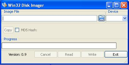 Win32 Disk Imager
 - In the Image File field, point to
RaspPi_Thread_Border_Router_Demo_v0.8.0-1.alpha.img. - In the Device field, select a device that corresponds to the microSD memory card that you connected to the computer.
- Warning
- If you choose an incorrect device, you may overwrite a partition on your computer or another device. Verify your choice by checking the letter mapped to the microSD card in My Computer.
- Click Write.
- After the image has been flashed, safely remove the microSD card from your computer. To do this, right-click the USB symbol in the taskbar and click Eject on the volume that represents the SD card.
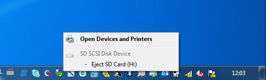 Safely remove the microSD card
 - Insert the microSD card into your Raspberry Pi.
Flashing the Network Co-Processor to the nRF52480 Development Kit
- Connect the nRF52840 Development Kit to the computer and power it on.
- Open the terminal (e.g. by pressing Windows Key + R and running
cmd). - Run the following command: nrfjprog --chiperase --family NRF52 --program <path_to_sdk>/examples/thread/experimental/ncp/hex/nrf52840_xxaa.hex
Starting the Border Router
- Connect the nRF52840 Development Kit to the Raspberry Pi using the microUSB – USB cable.
- Connect the Raspberry Pi through an Ethernet cable to your switch/router that provides IPv4 connectivity with the DHCP server enabled.
- Power on the nRF52840.
- Connect the microUSB power supply to the Raspberry Pi. The Border Router will start booting. Depending on your microSD card speed, the Border Router should be fully operational within two minutes.
 Starting the Border Router
Thread Settings:
The following are the default settings of the Border Router:
To customize the Thread settings, you must connect to the Border Router using SSH. This requires setting a password, which can be done in the LuCI configuration panel.
Because the Border Router received its IPv4 address dynamically using DHCPv4, you must log in to the router and check its address. Alternatively, you can use scanning software like Advanced IP Scanner. When the IPv4 address is known to you, open an Internet browser and go to this address. The LuCI configuration panel opens. The default logging credentials are: id: "root" and empty password. Change the password to a non-empty value.
Log in to the router using SSH. Vim and nano text editors are available on the Border Router. To change the settings, edit the /etc/config/thread_border_router file. The following lines can be found at the top of the file:
Edit these variables to customize the Thread configuration.
Connectivity:
NAT64 technology is enabled by default. It is used to enable communication between the IPv6-only Thread network with pure IPv4 LAN network that the Border Router connects to, as is the case in most applications. In that way, Thread nodes are able to connect to IPv4 cloud services. Thread devices will receive a NAT64-prefix and use it to create their own Unique Local Address.
The other connectivity option, which is also enabled by default, is support for the native IPv6 connection. It uses built-in DHCPv6 client on the Border Router which is able to receive prefixes from the Ethernet interface. If the received prefix is shorter than 63 bits, the 64-bit long subnet prefix is created and forwarded to the Thread network. In such situation, devices create one more address based on the forwarded prefix, which, unlike in a pure NAT64 solution, allows them to be reached from the Internet.
Testing
To test the Border Router, you can use another node with command line interface (CLI) and ping the Google DNS 8.8.8.8.
- Flash another nRF52840 Development Kit with nrfjprog, as described in Thread CLI Example. This time, use the following command: nrfjprog --chiperase --family NRF52 --program <path_to_sdk>/examples/thread/experimental/cli/hex/nrf52840_xxaa.hex --reset
- Start a terminal emulator like PuTTY and connect to the used COM port with the following UART settings:
- Baud rate: 115.200
- 8 data bits
- 1 stop bit
- No parity
- HW flow control: None
- PuTTy must be configured in two steps. First, in the Session tab, set the the Serial line, Speed, and Connection Type values.
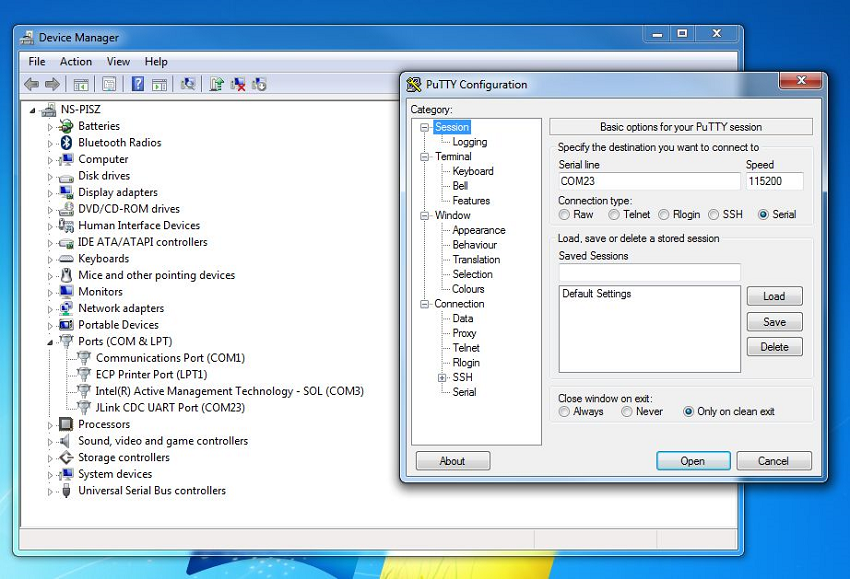 First step of PuTTY configuration
 - Then, in the Connection -> Serial tab, set the remaining parameters, i.e. Data bits, Stop Bits, and Flow control.
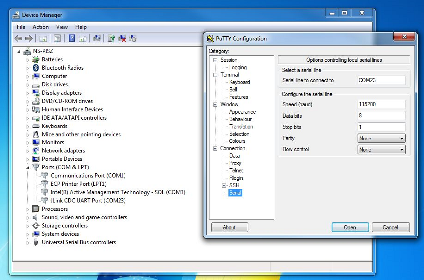 Second step of PuTTy configuration
- After the console window appears, press Enter. If the prompt mark ">" appears, the serial connection has been established. When a command is executed successfully, ">Done" is reported.
- Run the following commands: panid 0xabcdifconfig upthread startstateping fd00:0064:0123:4567::0808:0808
- Note
- 0808:0808 is in fact the Google DNS server address "8.8.8.8" coded in an appropriate way.
- After running the command, you should receive the following result: 16 bytes from fd00:64:123:4567:0:0:808:808: icmp_seq=5 hlim=39 time=111ms