Table of Contents
Thread Border Router serves as a gateway between the Internet and the Thread network. There are two ways of connecting the Thread Border Router to the Internet. The first one uses the standard Ethernet cable with an RJ-45 plug, while the other one uses a built-in Wi-Fi module.
The Border Router is intended for development purposes, to make it easy for developers to connect their Thread network to the Internet in the development phase. It also supports the Thread native commissioning procedure utilizing NFC to initiate the process. The Border Agent functionality is also supported, which allows for performing an external commissioning procedure as described in Commissioning.
The Border Router consists of Raspberry Pi 3 B, NXP Semiconductors' NFC reader shield, and Nordic’s nRF52840 Development Kit. The NXP Semiconductors' NFC reader shield is an optional element required for Thread native commissioning. However, the shield is not necessary to connect a Thread network to the Internet.
nRF52840 Development Kit acts as a connectivity chip running the Network Co-Processor (NCP) application. It communicates with Raspberry Pi using the Spinel protocol.
Raspberry Pi firmware is based on Raspbian (distribution 2017-11-29) and contains several deamons for controlling the NCP and the NFC reader shield, such as wpantund on GitHub and NFC commissioning deamon. For more information regarding the Nordic OpenThread Border Router build, refer to README.md.
For your convenience, this SDK provides pre-built, ready-to-use binary images for both nRF52840 and Raspberry Pi. The binary image intended for the Border Router is distributed under a license that is provided together with the Border Router image file. The EXPLORE_NFC_WW license applies if you use the Border Router feature to natively commission nodes using NFC. Licenses can be found in the package containing the Border Router binary image.
Required hardware
- Raspberry Pi 3 B
- nRF52840 Development Kit
- 4 GB (or larger) microSD card with SD card adapter
- microUSB power supply for Raspberry Pi 3 B
- microUSB to USB cable for connecting the nRF52840 Development Kit to the Raspberry Pi
- Computer running the Windows operating system with SD card slot or SD/microSD USB adapter
- Note
- Windows is used in this procedure but Linux and macOS operating systems are also supported.
- Optional: EXPLORE-NFC-WW Raspberry Pi shield - required for running the Thread NFC MeshCoP Example.
- Optional: Additional nRF52840 Development Kit for Border Router testing - a client that can connect to the Internet using the Border Router.
- Optional: Android Device for external commissioning testing.
Required software
- Win32 Disk Imager
- nrfjprog – available in nRF5x-Command-Line-Tools-Win32 from the nRF52840 product website
- Terminal client with serial connection support, such as PuTTy
- Border Router Raspberry Pi image available from nRF5 SDK for Thread web page "nRF5 SDK for Thread and Zigbee v1.0.0 web page" -
RaspPi_OT_Border_Router_Demo_v1.0.0-1.alpha.img - NCP example located in
<InstallFolder>\examples\thread\ncp - CLI example located in
<InstallFolder>\examples\thread\cli
Setup procedure
Complete the following steps to set up the Border Router solution.
Flashing the Raspberry Pi image to the microSD card
- Install microSD card in your computer and start the Win32 Disk Imager.
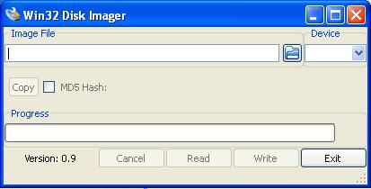 Win32 Disk Imager
 - In the Image File field, point to
RaspPi_OT_Border_Router_Demo_v1.0.0-1.alpha.img. - In the Device field, select a device that corresponds to the microSD memory card that you connected to the computer.
- Warning
- If you choose an incorrect device, you may overwrite a partition on your computer or another device. Verify your choice by checking the letter mapped to the microSD card in My Computer.
- Click Write.
- After the image has been flashed, safely remove the microSD card from your computer. To do this, right-click the USB symbol in the taskbar and click Eject on the volume that represents the SD card.
- Insert the microSD card into your Raspberry Pi.
Flashing the Network Co-Processor to the nRF52480 Development Kit
- Connect the nRF52840 Development Kit to the computer and power it on.
- Open the terminal (e.g. by pressing Windows Key + R and running
cmd). - Run the following command. nrfjprog --chiperase --family NRF52 --program <InstallFolder>/examples/thread/ncp/uart/hex/nrf52840_xxaa.hex
- Note
- You can also use either the USB CDC version or the SPI version of the NCP example. Keep in mind though, that if the USB version is selected, you must use the native nRF USB port. To set up the SPI version, refer to Network Co-Processor over SPI communication.
Network Co-Processor over SPI communication
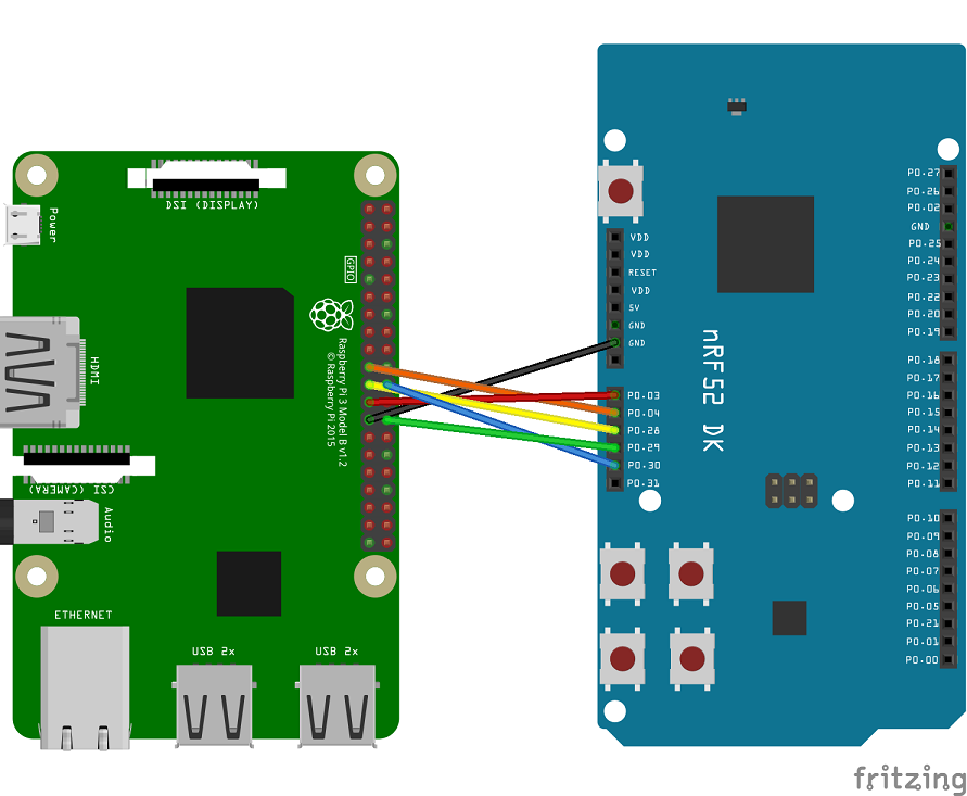
The Network Co-Processor can also be connected to the Border Router over SPI protocol with the NCP application acting as an SPI slave and the Border Router as an SPI master device. To set up this configuration, complete the following steps.
- The Border Router and the nRF52840 Development Kit hosting the NCP application must have their SPI pins physically connected,
- the SPI peripheral must be enabled and properly configured on the Border Router,
- the SPI version of the NCP example must be flashed to the nRF52840 Development Kit.
Pin connection
To establish an SPI connection, the following pins must be connected: MOSI (Master Out Slave In), MISO (Master In Slave Out), SCK, CSN, and INT. The INT pin is optional, but the lack of it significantly reduces performance of the communication. The Raspberry Pi has predefined SPI pins that can be found in its datasheet. SPI pins on the nRF52840 can be configured when building the example. The default configuration can be found in the table below. As an example, a schematic created with Fritzing is also shown, which uses the default configuration.
| SPI pin | Raspberry Pi pin | nRF52840 pin |
|---|---|---|
| MOSI | pin 19 (GPIO10) | P0.04 |
| MISO | pin 21 (GPIO09) | P0.28 |
| SCK | pin 23 (GPIO11) | P0.03 |
| CSN | pin 26 (GPIO07) | P0.29 |
| INT | pin 22 (GPIO25) | P0.30 |
Border Router SPI configuration
The SPI peripheral is enabled by default on the Border Router. You can verify that by checking that the /dev/spidev0.0 and /dev/spidev0.1 devices are visible. However, when the NCP is connected with SPI to the Border Router, automatic detection of NFC shields should be disabled on the Border Router. To disable automatic detection of an NFC shield, log in to the Border Router and type the following command:
Additionally, there is a jlink_config service which searches and configures J-Link connections. When the NCP is connected with SPI to the Border Router, there is no J-Link connected device. As the jlink_config service can affect the wpantund daemon initialization time, it should be disabled. To do that, use the following command:
With the SPI peripheral enabled, SPI must be chosen as the transport protocol for wpantund, a daemon managing the Network Co-Processor. Its configuration can be found in /etc/wpantund.conf. To set SPI as the transport protocol, an appropriate SPI device must be chosen as the NCP socket in the configuration file. See the example configuration below.
spi-hdlc-adapter is a tool that is used to perform communication between wpantund and NCP. It is assumed in the above example that spi-hdlc-adapter is installed in /usr/bin/ and that the INT pin is connected to GPIO25 on the Raspberry Pi.
Starting the Border Router
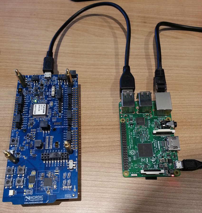
- Connect the nRF52840 Development Kit to the Raspberry Pi using the microUSB – USB cable.
- Connect the Raspberry Pi through an Ethernet cable or WiFi to your switch/router that provides IPv4 or IPv6 connectivity with the DHCP or DHCPv6 service respectively.
- Power on the nRF52840.
- Connect the microUSB power supply to the Raspberry Pi. The Border Router will start booting. Depending on your microSD card speed, the Border Router should be fully operational within two minutes.
 Starting the Border Router
Thread Settings
The following are the default settings of the Border Router.
Connectivity
NAT64 technology is enabled by default. It is used to enable communication between the IPv6-only Thread network with pure IPv4 LAN network that the Border Router connects to, as is the case in most applications. In that way, Thread nodes are able to connect to IPv4 cloud services.
The other connectivity option, which is also enabled by default, is support for the native IPv6 connection. It uses built-in DHCPv6 client on the Border Router which is able to receive prefixes from the Ethernet interface. If the received prefix is shorter than 63 bits, the 64-bit long subnet prefix is created and forwarded to the Thread network. In such situation, devices create one more address based on the forwarded prefix, which, unlike in a pure NAT64 solution, allows them to be reached from the Internet.
- Note
- When dealing with native IPv6 connectivity, make sure you use the DHCPv6 service, and not the popular Stateless Address Autoconfiguration (SLAAC) tool. This autoconfig tool will only provide a 64-bit long prefix that is not sufficient to delegate a new 64-bit long prefix for the Thread network.
Support for Domain Name System (DNS) resolution is also available. This mechanism is used to translate a host name into a corresponding IP address. It can be used either for translating a domain name into its native IPv6 or for obtaining its IPv4 address and returning IPv6 translated with the DNS64 mechanism.
Testing
To test the Border Router, you can use another node with command line interface (CLI) and ping the Google DNS server 8.8.8.8.
- Flash another nRF52840 Development Kit with nrfjprog, as described in Thread CLI Example. This time, use the following command. nrfjprog --chiperase --family NRF52 --program <InstallFolder>/examples/thread/cli/uart/hex/nrf52840_xxaa.hex --reset
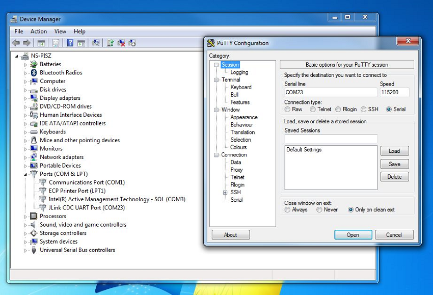
- Start a terminal emulator like PuTTY and connect to the used COM port with the following UART settings:
- Baud rate: 115.200
- 8 data bits
- 1 stop bit
- No parity
- HW flow control: None
- PuTTy must be configured in two steps. First, in the Session tab, set the the Serial line, Speed, and Connection Type values.
 First step of PuTTY configuration
 - Then, in the Connection -> Serial tab, set the remaining parameters, i.e. Data bits, Stop Bits, and Flow control.
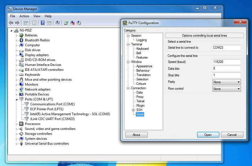 Second step of PuTTy configuration
- After the console window appears, press Enter. If the prompt mark ">" appears, the serial connection has been established. When a command is executed successfully, ">Done" is reported.
- Run the following commands. panid 0xabcdifconfig upthread startstateping 64:ff9b::0808:0808
- Note
- 0808:0808 is in fact the Google DNS server address "8.8.8.8" in hex representation. In that way, you can reach any IPv4 cloud by replacing last 32 bits of an IPv6 address with a correctly encoded IPv4 address.
- After running the command, you should receive the following result. 8 bytes from 64:ff9b:0:0:0:0:808:808: icmp_seq=1 hlim=56 time=55ms
- Obtain the addresses of the connected node by typing
ipaddr.> ipaddr2001:db8:dead:beef:98ba:8f31:fc05:6919fd11:22:0:0:b85d:8ff4:3011:3797fdde:ad00:beef:0:bebd:ae25:a6c7:a0b5fdde:ad00:beef:0:0:ff:fe00:b001fe80:0:0:0:a4aa:fd14:d403:89d6Done- Note
- There may be more IPv6 addresses assigned to the interface. It depends on the configuration of the routers on the link from which the Border Router gets IPv6 prefixes. If IPv6 connectivity is present, the device will obtain the global IPv6 address starting with a
2000::/3prefix, in this example 2001:db8:dead:beef:98ba:8f31:fc05:6919. This address can be used to reach the node from any IPv6-connected device. The simplest test is to ping this address from a computer connected to the IPv6 network.
- You can use DNS to resolve the native IPv6 address of the given host name in the following way. If the host does not have IPv6 connectivity, a Thread device may still connect with a IPv4 cloud utilizing the NAT64 and DNS64 protocols. To obtain a a translated IPv6 address, you must specify the DNS resolver fdaa:bb:1::1 which is running on the Thread Border Router, as shown below.> dns resolve ipv6.google.com> DNS response for ipv6.google.com - [2a00:1450:401b:802:0:0:0:200e] TTL: 299> ping 2a00:1450:401b:802:0:0:0:200e> 8 bytes from 2a00:1450:401b:802:0:0:0:200e: icmp_seq=2 hlim=55 time=42msError 25 indicates that there is no IPv6 address returned as the ipv4.google.com does not have any.> dns resolve ipv4.google.com> DNS response for ipv4.google.com - Error 25> dns resolve ipv4.google.com fdaa:bb:1::1> DNS response for ipv4.google.com - [64:ff9b:0:0:0:0:d83a:d5ee] TTL: 300> ping 64:ff9b:0:0:0:0:d83a:d5ee> 8 bytes from 64:ff9b:0:0:0:0:d83a:d5ee: icmp_seq=3 hlim=50 time=87ms
Thread Border Router Wi-Fi usage and configuration
In a typical use case, it is assumed that no additional communication interface is present. In such scenario, Thread Border Router starts in Access Point mode, advertising its own Wi-Fi network called "BorderRouter-AP". A user connects to this network and chooses a local Wi-Fi network for the Thread Border Router to connect to.
After each reboot, the Border Router enables Access Point mode and advertises the "BorderRouter-AP" network.
When the Access Point is enabled, the following steps are required to connect the Thread Border Router to the specified Wi-Fi network in a client mode.
- Connect to the Nordic Thread Border Router Wi-Fi network. SSID: BorderRouter-APPassword: 12345678
- Open an SSH client and connect to the address 10.42.0.1. Username: piPassword: raspberry
- To get a list of available Wi-Fi networks, enter the following command. pi@raspberrypi:~$ sudo iwlist scan | grep SSIDlo Interface doesn't support scanning.wpan0 Interface doesn't support scanning.ESSID:"Linksys"ESSID:"TS_WiFi_2_4_GHz"eth0 Interface doesn't support scanning.nat64 Interface doesn't support scanning.
- Enter the following command to connect to the selected Wi-Fi network. pi@raspberrypi:~$ wifi_connect <SSID> [password]
- Note
passwordis an optional parameter that must be provided if the selected network is protected by WPA-PSK encryption.
If connecting to the selected Wi-Fi network fails, the Border Router enables the Access Point again.
Running MQTT-SN Gateway on Thread Border Router
The MQTT-SN Gateway used in the Thread MQTT-SN Example can be run on the Thread Border Router. The MQTT-SN Gateway is enabled by default. To disable the MQTT-SN Gateway, the following command should be run.
With this option enabled, MQTT-SN Gateway starts automatically once you reboot the Raspberry Pi. The gateway has already been configured to work correctly with the Thread MQTT-SN Example.
Configuration of the MQTT Broker
The configuration file for the Paho MQTT-SN Gateway is located in /etc/paho-mqtt-sn-gateway.conf. By default, the IPv4 address of the Eclipse IoT MQTT Broker is used. You may want to use another MQTT Broker. To do that, modify the BrokerName and BrokerPortNo variables in the configuration file.
Note that you need to type the IPv4 address of the MQTT Broker. The host name representation is currently not supported.
Commissioning
The Nordic Border Router, which is based on the OpenThread Border Router (OTBR), supports both native and external commissioning.
In native Thread Commissioning, the Thread Leader authenticates a user (external Commissioner) or a Thread device onto the Thread network. After authentication, the Commissioner instructs the Joiner Router to transfer Thread network credentials, such as the master key, directly to the device. In this type of commissioning, Thread network credentials are transferred between devices over the radio. For information on Native Thread Commissioning with NFC, see Thread NFC MeshCoP Example.
In external Thread Commissioning, a device outside of the Thread network (for example, a mobile phone) commissions new devices onto the network. This guide describes external Thread Commissioning with the use of the Thread App for Android.
- Note
- During commissioning, the Thread Commissioner never gains possession of the network master key.
This guide details how to use the Thread Commissioning App to commission the Nordic CLI example device onto the Thread Network.
Forming the Thread network
- Prepare the Border Router as described in Setup procedure.
- Flash an nRF52840 Development Kit with the CLI example. You can use either the UART or the USB version. nrfjprog --chiperase --family NRF52 --reset --program <InstallFolder>/examples/thread/cli/uart/hex/nrf52840_xxaa.hex
- Once the Joiner device is ready, obtain its IEEE EUI-64. To do this, use the eui64 command in the OpenThread CLI. > eui6414def7d76bbd2876Done
- Download the Thread Commissioning App.
- Note
- External commissioning is supported by the Thread Commissioning App, available for download for Android devices in the Google Play Store. This app is only available for Android.
- Start the Thread Commissioning App.
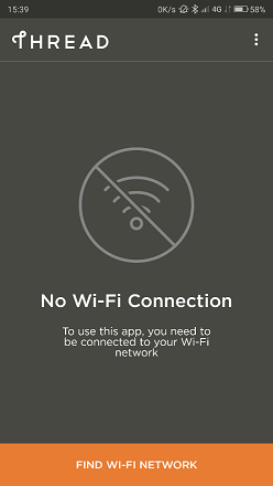 Start the app
- Tap FIND WI-FI NETWORK and connect the device running the Thread Commissioning App to the Wi-Fi access point.
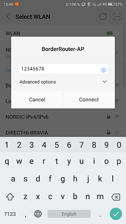 Connect to the Wi-Fi access point
- Note
- The smartphone running the Thread Commissioning App and the Thread Border Router must be connected to the same Local Area Network. In this example, the smartphone is connected to the Access Point on your Thread Border Router, but you may as well connect the Border Router to your Local Network (either using Wi-Fi or Ethernet) together with your smartphone. In the latter case, the joining node will be able to connect to the Internet through the Border Router.
- Select the target Border Router from the available list. The name is the same as the Thread network created by the OTBR Web GUI. If the same Border Router shows up multiple times with different IPv4 and IPv6 addresses, select the one with the static IPv4 address used for the Wi-Fi access point setup (10.42.0.1 in this case).
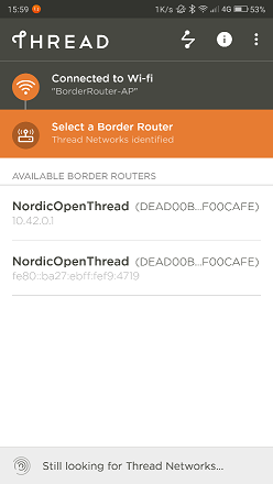 Select the Border Router to connect to
- When prompted for a password, enter the passphrase 123456 (Commissioner Credential).
The passphrase 123456 is automatically configured during the autostart procedure. It may differ if it has been changed in the Form Network section in the web panel.
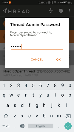 Enter the passphrase
- Commission the Joiner.
 Commission the Joiner
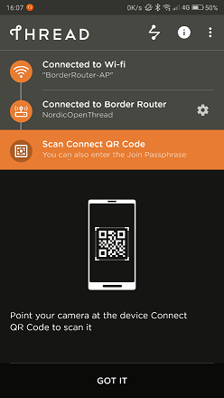
Once connected to the Border Router, the app provides the option to scan a Connect QR Code or enter a Join Passphrase manually. - Optional: Generate a QR code.
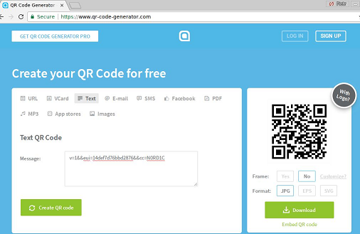 Generate a QR code
Thread Connect QR Codes are created with the following text string format:, where eui is the Joiner device's EUI64 value and cc is the Joiner Credential. Use this text string with an online QR Code generator to create a QR Code for scanning.v=1&&eui=14def7d76bbd2876&&cc=N0RD1C- Note
- The Joiner Credential is a device-specific string of all uppercase alphanumeric characters (0-9 and A-Y, excluding I, O, Q, and Z for readability), with a length between 6 and 32 characters.
- Scan the QR code or manually enter the EUI64 and Joiner Credential.
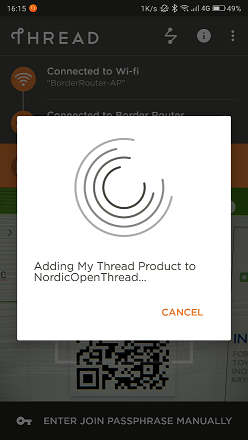 Adding the Joiner to the Thread Network
Scanning the Connect QR Code or manually entering the credentials generates the PSKd, which propagates the steering data through the Thread network. - Start the Joiner.
While the app is waiting, enter the OpenThread CLI on the Joiner device and start the Joiner role with the same Joiner Credential.Wait a minute for the DTLS handshake to complete between the Commissioner and Joiner.> ifconfig upDone> joiner start N0RD1CDone>Join success!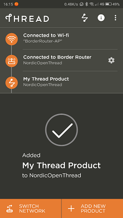 Joiner added to the Network
The Thread Commissioning App displays an "Added My Thread Product" confirmation message.
The Joiner has obtained the Thread network credentials and can now join the network. - Join the network. On the Joiner device, start the Thread protocol to automatically join the network. Check the state after a few moments to confirm. It may initially start as a Child, but within two minutes, it will upgrade to a Router.> thread startDoneCheck the IPv6 addresses of the device. If the Nordic Border Router is connected to the Internet, the Joiner will have the ability to connect with the outside world. In case there is a native IPv6 connection with prefix equal or shorter than /63 available for the Border Router, it will assign the /64 global pool for the Thread Network. In case of lack of a proper prefix, NAT64 can still be used with the local IPv4 connection.> staterouterDone> ipaddrfdde:ad11:11de:0:0:ff:fe00:9400fd11:22:0:0:3a15:3211:2723:dbe1fe80:0:0:0:6006:41ca:c822:c337fdde:ad11:11de:0:ed8c:1681:24c4:3562
- Ping the Internet.
Test the connectivity between the Joiner device in the Thread network and the Internet by pinging a public IPv4 address.
To reach the IPv4 address from the Thread device, a Well-Known Prefix of 64:ff9b::/96 and an IPv4 address of the destination are used.
To ping Google’s DNS 8.8.8.8 from the IPv6 address, append a hexadecimal form of the IPv6 to the Well-Known Prefix resulting in:64:ff9b::808:808.
Ping this address from the device running the Nordic CLI example (the Joiner):> ping 64:ff9b::808:808> 8 bytes from 64:ff9b:0:0:0:0:808:808: icmp_seq=3 hlim=45 time=72ms