Important: Before you run this example, make sure to program the SoftDevice.
Advanced burst data transmission provides a mechanism to transfer bulk data with a maximum data throughput of 60 kbps. The transmission rate, along with optional features such as frequency hopping, is negotiated over the air, offering backwards compatibility with implementations supporting only standard burst. In order to sustain this data throughput, the application must ensure that data is available for transmission on a timely basis; one mechanism available to achieve this is buffering. ANT SoftDevices provide a burst handler that can queue arbitrary amounts of burst data for transmission by passing an input buffer with the data to send. While it is possible to place the entire burst data in the input buffer, this may not be a feasible option for large amounts of data due to RAM limitations.
The purpose of this example is to demonstrate how to send and receive large amounts of burst data while buffering smaller blocks of data (128 bytes) at a time. This example shows how to process the different ANT events to queue the next block of data for optimal throughput, as well as to determine the success or failure of the burst transfer. This example also shows how to split received advanced burst data into 8-byte segments, resembling standard burst messages. For more details on burst transfers, please refer to the application note ANT AN Burst Transfers.
This example is intended to be paired with an ANT USB stick and the ANTware II PC application configured as a slave.

Operation
After start up, this example will configure and open an ANT master channel with the following channel parameters:
Table 1. Channel Parameters
| Parameter | Value |
|---|---|
| Channel Type | Master (0x10) |
| Extended Assignment | 0 |
| Network | Public |
| Radio Frequency | 66 |
| Device Number | Serial Number |
| Device Type | 2 |
| Transmission Type | 1 |
| Channel Period | 8192 (4 Hz) |
In addition to this, the example enables advanced burst with the following parameters:
Table 2. Advanced burst configuration
| Parameter | Value |
|---|---|
| Enable | ADV_BURST_MODE_ENABLE |
| RF payload size | ADV_BURST_MODES_MAX_SIZE (24 bytes) |
| Required Features | 0 (none) |
| Optional Features | 0 (none) |
Refer to Section 9.5.2.27 of the ANT Message Protocol and Usage document for more details on the different parameters used when configuring advanced burst. Pressing BSP_BUTTON_0 will send a burst transfer with BURST_TOTAL_PACKETS 8-byte packets. The burst is filled with dummy data. BSP_LED_0 will turn on while a burst is in progress (either transmitting or receiving), while BSP_LED_1 will turn on if the burst failed to complete successfully.
Setup
You can find the source code and project file of the example in the following folder: <InstallFolder>\examples\ant\experimental\ant_advanced_burst
Testing
- Compile and program the ant_advanced_burst application onto the module.
- Plug in an ANT USB stick into the computer.
- Open the ANTware II tool.
- Configure the device channel by loading the device profile configuration from the following file:
<InstallFolder>\examples\ant\experimental\ant_advanced_burst\ant_advanced_burst_device_profile.xml.
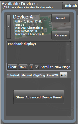
Alternatively, you can configure the device channel manually:- Expand the device panel and select the “Adv” tab.
- Click on “Show Advanced Device Panel”
- Select the “Adv. Burst” tab, and select the “Standard” tab under it.
- Configure Pckts/AntMsg to 3 and select Enable.
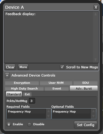
- Click “Set Config”
- Configure Channel 0 as a Slave. Click “Assign”.
- Configure the Device Type and Transmission Type as in Table 1. Set the device number to 0 (wild card).
- Configure the radio frequency as in Table 1.
- Configure the channel period as in Table 1.
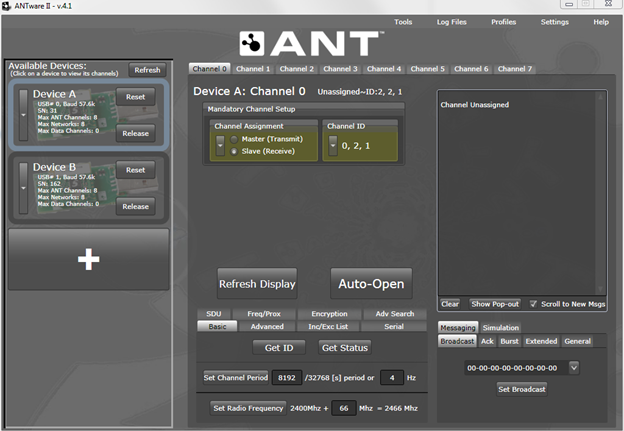
- Click “Auto Open”
- Press BSP_BUTTON_0 in the development board. ANTware II will show the received burst data. BSP_LED_0 will turn on during the burst transfer.
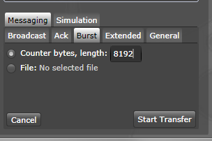
- Select the “Messaging” tab on ANTware II, and click on the “Burst” tab.
- Select the “Countr bytes” option, and set the length to 8192.
- Click “Start Transfer”
- On the development board, BSP_LED_0 will turn on while the transfer is in progress. ANTware II will show that the burst was transmitted, whether it was successful or not, and the time spent during the transfer.