Purpose
This demo project shows how a PTM215B EnOcean switch can be integrated in the mesh eco system.
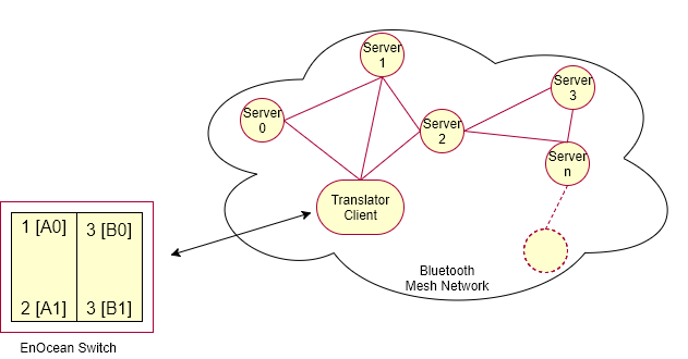
It demonstrates how to capture the commissioning data of the EnOcean switch and how to translate the EnOcean switch messages into equivalent mesh messages. It uses two instances of the Generic OnOff client model. These On/Off clients can be configured to control desired servers by the provisioner. Following diagram shows the illustration of such hybrid network containing non-Bluetooth Mesh device, translator client, and servers. All servers have relay functionality enabled thereby allowing EnOcean switch to control state of any of the servers in the network.
To see the demonstration, this example has to be used with a Provisioner and one or more Servers from the light_switch examples folder.
Getting started
Hardware requirements
See compatiblity section for the supported boards.
- One development board for this example.
- One development board for the provisioner.
- One or more development boards for the servers. If you have more than thirty boards for the server, set
SERVER_NODE_COUNT(inlight_switch_example_common.h) to the number of boards available and rebuild the provisioner example.
Running the demo
To build the example, follow the instructions in Building the Mesh Stack. Refer to the How to run examples section in Examples README for the commands required to program a device using nrfjprog.
- Erase the device flash of your development board, and program the SoftDevice on each board.
- Flash the provisioner firmware on one board and the server firmware on other boards. Do not start the provisioning process yet. (You can also capture the commissioning data of the EnOcean switch after translator client has been provisioned.)
- Flash this example on one board.
- Connect RTT viewer to view the RTT output generated by the translator client and the provisioner.
Put the EnOcean switch in the radio based commissioning mode by pressing the special button sequence as follows:
To enter commissioning mode, start by selecting one button contact of PTM 215B. Any button of PTM 215B (A0, A1, B0, B1) can be used. This button is referred to as Button_X in Figure 20 above.
Next, execute the following long-short-long sequence:
- Press and hold the selected button for more than 7 seconds before releasing it.
- Press the selected button quickly (hold for less than 2 seconds).
- Press and hold the selected button again for more than 7 seconds before releasing it.
Upon detection of this sequence, PTM 215B will enter commissioning mode if the Disable Radio Commissioning flag in the Configuration register of the NFC interface is set to 0b0 (default state). Reference: EnOcean PTM215B Datasheet
Once entered in the radio commissioning mode, PTM215B will transmit commissioning telegrams. These telegrams will be captured by the translator, and the security material contained within those telegrams will be stored in the flash. Once the commissioning telegram is captured by the translator, LED 1 will blink twice.
The example supports two Enocean switches to be connected in parallel. You can repeat the above mentioned steps to commission the second switch.
- Press Button 1 on the provisioner to start the provisioning process.
The provisioner prints details about the provisioning and the configuration process in the RTT log. When provisioner is scanning and provisioning a device, LED 1 on the Provisioner board is turned ON. When configuration procedure is underway, LED 2 on the provisioner board is turned ON.
The provisioner configures the On/Off client model instances on the client board to control various servers as follows:
- The Button A0 turns ON LED 1 on the servers with Odd addresses.
- The Button A1 turns OFF LED 1 on the servers with Odd addresses.
- The Button B0 turns ON LED 1 on the servers with Even addresses.
- The Button B1 turns OFF LED 1 on the servers with Even addresses.
Once provisioning and configuration of the EnOcean translator client node and at least one of the server nodes is completed, you can press buttons on the EnOcean switch to toggle the LED state on the associated servers.
If any of the devices are powered off and back on, they will remember their configuration in flash, and rejoin the network. More information about the flash manager can be found in the flash manager documentation.
If provisioner encounters an error during the provisioning or configuration process for a certain node, you can reset the provisioner to restart this process for that node.
Any unhandled error is indicated by turning on all the LEDs on the board in steady state. You will need to reset the board to restart the application.
Details
For details about the provisioning and configuration process, see the Exploring Mesh APIs guide. See Light switch demo README to get more information about the provisioner and server examples.
EnOcean switch translator client
The EnOcean switch translator client has a provisionee role in the network. The client receives messages from the PTM215B switch and converts them to equivalent On/Off client messages to control the state of LED 1 on servers. It instantiates two instances of the Generic OnOff Client model. The provisioner configures these client model instances to communicate with servers.
The example is configured to store security material for two EnOcean switch. If you want to reset the application data without re-flashing the firmware, press Button 4. LED 1 will blink twice to indicate that application specific data and mesh related data has been erased. Press Reset button to reset the board and start the application.
If you want this example to support more than two EnOcean switches in parallel, set the value of MAX_ENOCEAN_DEVICES_SUPPORTED to the desired number of switches.